3-8 | ni.com
Chapter 3 I/0 Information
Universal Serial Bus
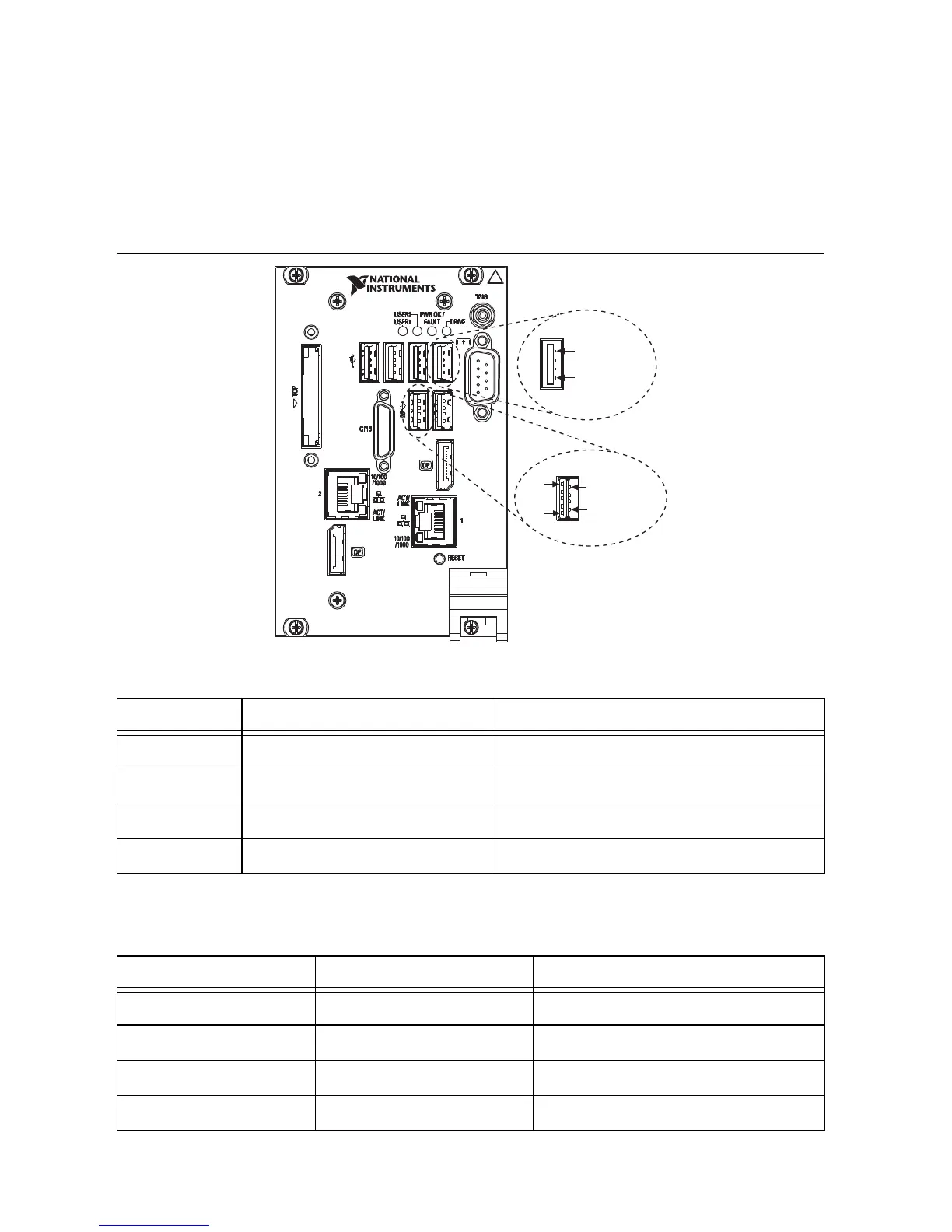
Figure 3-5 shows the location and pinouts for the Universal Serial Bus (USB) connectors on the
PXIe-8840. Each controller has four USB 2.0 ports and two USB 3.0 ports on the front panel.
Table 3-6 lists and describes the USB 2.0 connector signals. Table 3-7 lists and describes the
USB 3.0 connector signals.
Figure 3-5. USB Connector Location and Pinout
Table 3-6. USB 2.0 Connector Signals
Pin Signal Name Signal Description
1 VCC Cable Power (+5 V)
2 -Data USB Data -
3 +Data USB Data +
4 GND Ground
Table 3-7. USB 3.0 Connector Signals
Pin Signal Name Signal Description
1 VCC Cable Power (+5 V)
2 -Data USB Data -
3 +Data USB Data +
4 GND Ground
USB 2.0
4
1
9
5
4
1
USB 3.0
NI PXIe-8840
Embedded Controller

 Loading...