EasyManuals Logo

National Instruments PXIe-8840 User Manual

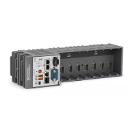
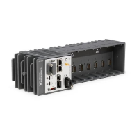
National Instruments PXIe-8840
66 pages
To Next Page IconTo Next Page
To Previous Page IconTo Previous Page
Page #40 background imageLoading...
Page #40 background image
3-4 | ni.com
Chapter 3 I/0 Information
COM1
Figure 3-3 shows the location and pinouts for the COM1 connector on the PXIe-8840. Table 3-3
lists and describes the COM1 connector signal.
Figure 3-3. COM1 Connector Location and Pinout
13 CONFIG1
14 CONFIG2
15 AUX CH (p)
16 GND
17 AUX CH (n)
18 Hot Plug Detect
19 Return
20 DP_PWR
Table 3-2. DisplayPort Connector Signals (Continued)
Pin Signal Name
5
1
6
9
COM1
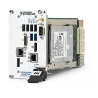
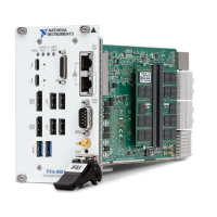
NI PXIe-8840
Embedded Controller

Table of Contents

Other manuals for National Instruments PXIe-8840

Questions and Answers:

Question and Answer IconNeed help?

Do you have a question about the National Instruments PXIe-8840 and is the answer not in the manual?

National Instruments PXIe-8840 Specifications

General IconGeneral
BrandNational Instruments
ModelPXIe-8840
CategoryController
LanguageEnglish

Related product manuals