3-6 | ni.com
Chapter 3 I/0 Information
Ethernet
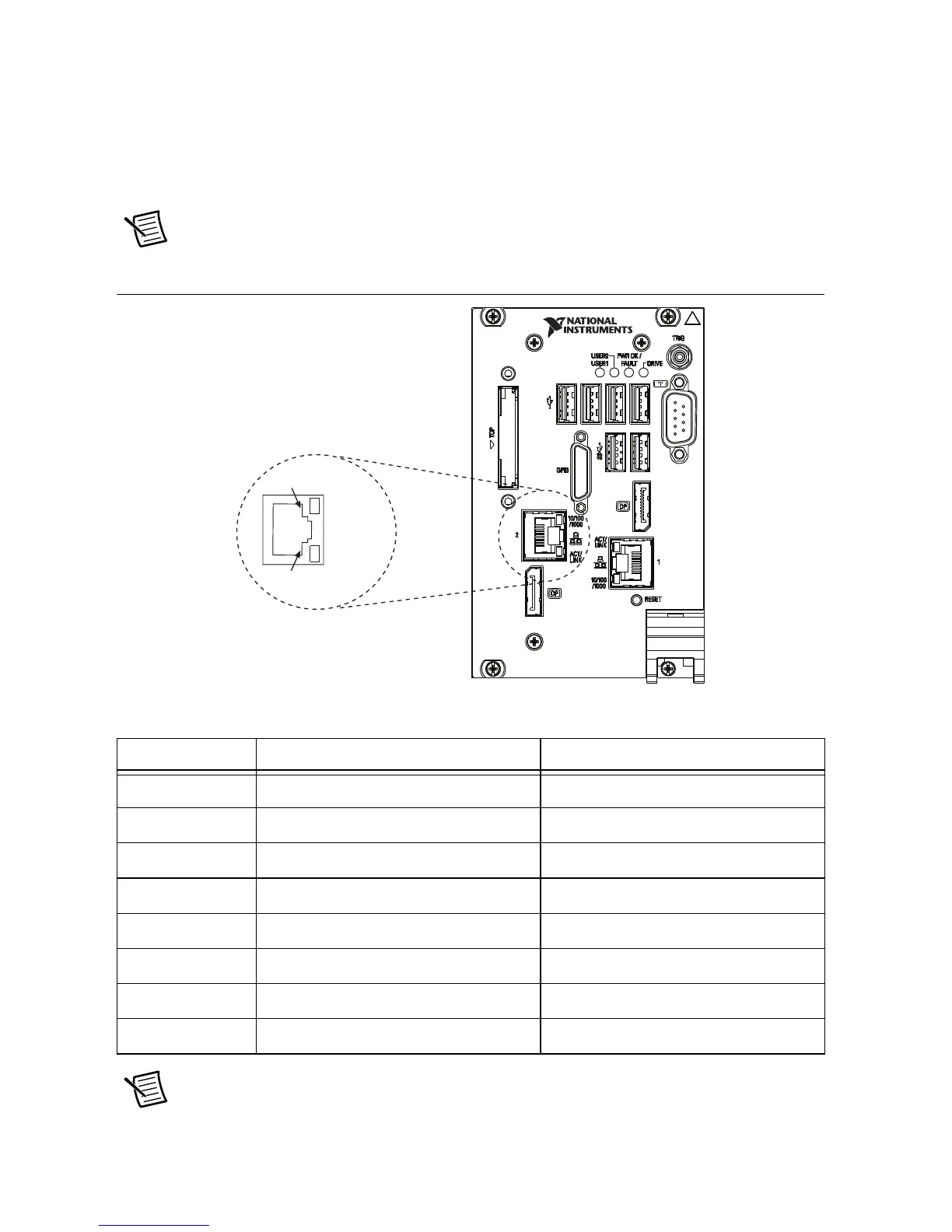
Figure 3-4 shows the location and pinouts for the Ethernet connector on the PXIe-8840.
Table 3-4 lists and describes the Ethernet connector signals. Table 3-5 lists and describes the
10/100/1000 LAN connector LED states.
Note The Wake On LAN feature is only supported by Ethernet Port 1.
Figure 3-4. Ethernet Connector Location and Pinout
Note The Ethernet controller can perform an automatic crossover, thus eliminating
the need for crossover cables.
Table 3-4. Ethernet Connector Signals
Pin Fast Ethernet Gigabit Ethernet
1 TX+ TX_A+
2 TX- TX_A-
3 RX+ RX_B+
4 NC TX_C+
5 NC TX_C-
6 RX- RX_B-
7 NC RX_D+
8 NC RX_D-
Ethernet
1
8
NI PXIe-8840
Embedded Controller

 Loading...