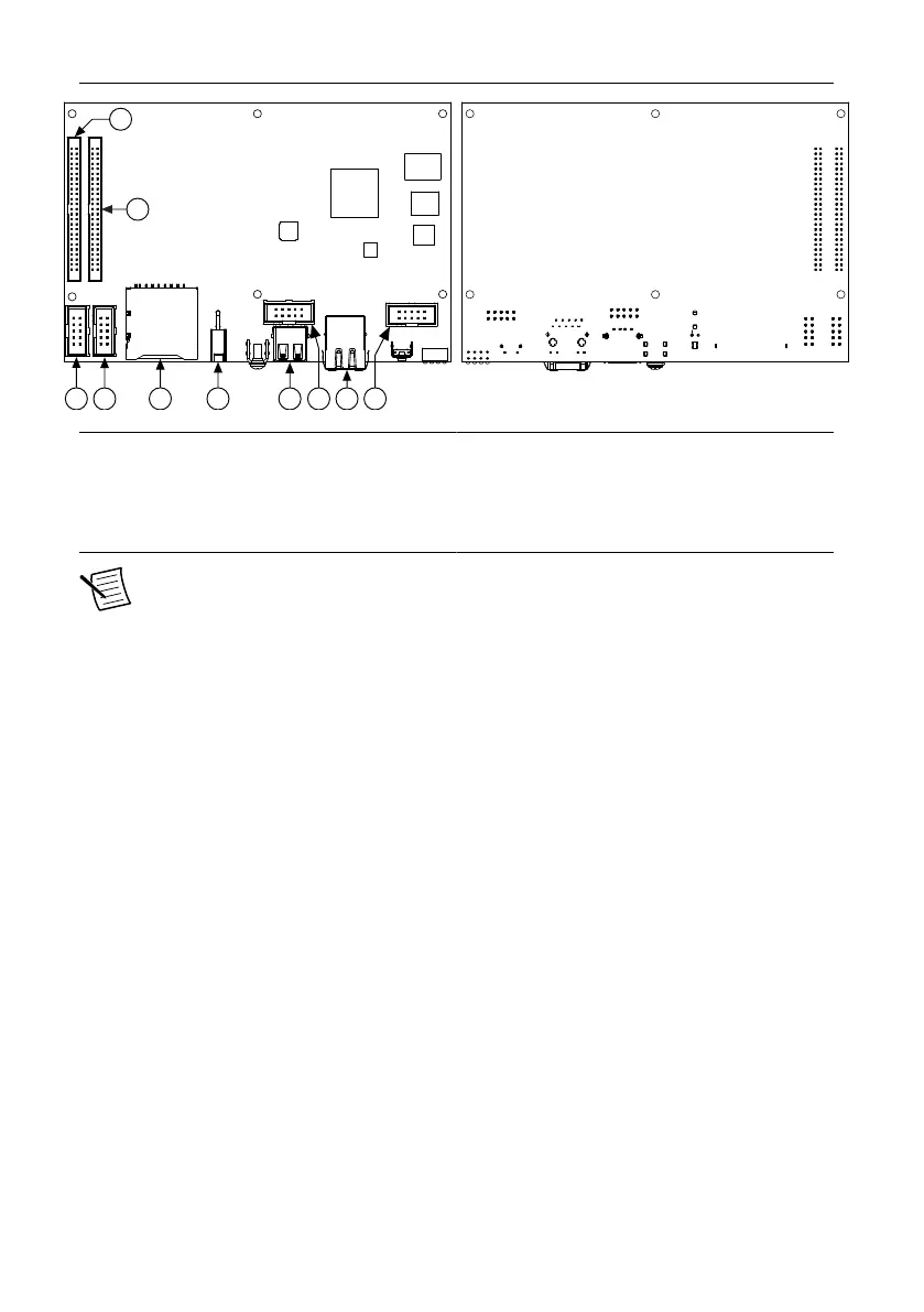
Figure 14. sbRIO-9637 Ports and Connectors
1. W3, RS-485 (ASRL3)
2. W4, RS-232 (ASRL2)
3. J6, SDHC
4. J9, Power Connector
5. J10, USB Host Port
6. W1, CAN (CAN0)
7. J7, RJ-45 Ethernet Port
8. W2, RS-232 (ASRL1)
9. J5, MIO
10. J4, DIO
Note Ethernet, CAN, RS-232, and RS-485 peripherals are all are routed through
the FPGA. These peripherals will be temporarily unavailable when the FPGA is
reconfigured. Downloading your FPGA application to the flash of the sbRIO-9637
ensures that the FPGA is configured before the driver can access a given peripheral.
Refer to the Configuring FPGA Startup App section in this document for more
information.
Connector Descriptions
The following table lists the connectors on the NI sbRIO device and the part number and
manufacturer of each connector. Refer to the manufacturer for information about using and
matching these connectors.
NI sbRIO-9637 User Manual | © National Instruments | 17
Artisan Technology Group - Quality Instrumentation ... Guaranteed | (888) 88-SOURCE | www.artisantg.com

 Loading...


