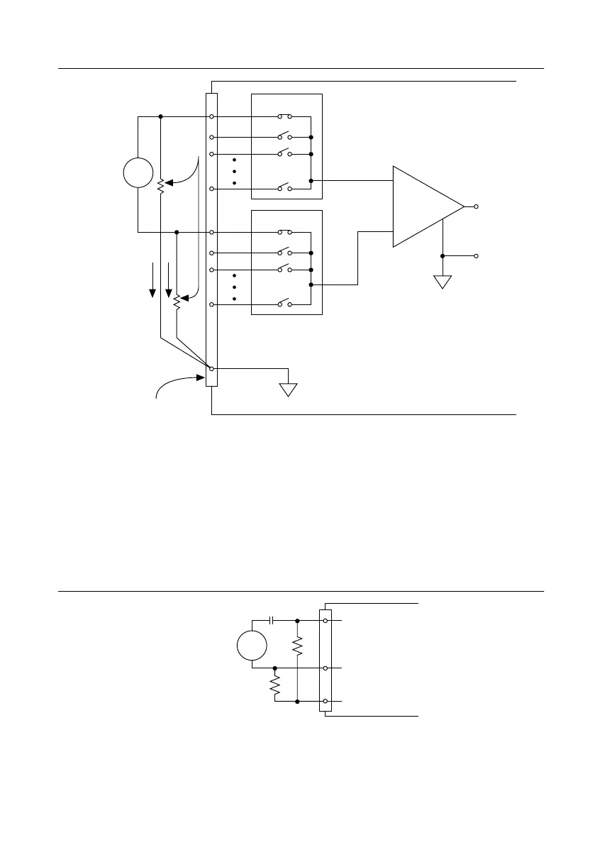
Figure 28. Differential Connections for Floating Signal Sources with Balanced Bias
Resistors
PGIA
–
+
–
+
–
+
Floating
Signal
Source
Bias
Current
Return
Paths
AI GND
Input Multiplexers
Measured
Voltage
Instrumentation
Amplifier
AI+
AI–
I/O Connector
Bias
Resistors
(see text)
V
s
V
m
Both inputs of the PGIA require a DC path to ground in order for the PGIA to work. If the
source is AC coupled (capacitively coupled), the PGIA needs a resistor between the positive
input and AI GND. If the source has low-impedance, choose a resistor that is large enough not
to significantly load the source but small enough not to produce significant input offset voltage
as a result of input bias current (typically 100 kΩ to 1 MΩ). In this case, connect the negative
input directly to AI GND. If the source has high output impedance, balance the signal path as
previously described using the same value resistor on both the positive and negative inputs.
Some gain error will occur as a result of loading down the source, as shown in the following
figure.
Figure 29. Differential Connections for AC Coupled Floating Sources with Balanced
–
+
AI GND
V
s
AC Coupled
Floating
Signal
Source
AI+
AI–
AC Coupling
36 | ni.com | NI sbRIO-9637 User Manual
Artisan Technology Group - Quality Instrumentation ... Guaranteed | (888) 88-SOURCE | www.artisantg.com

 Loading...


