Chapter 5 Adding Components for Special Functions
SCB-68 Shielded Connector Block User Manual 5-8 ni.com
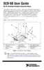
Figure 5-6. Transfer Function Attenuation for an Ideal Filter
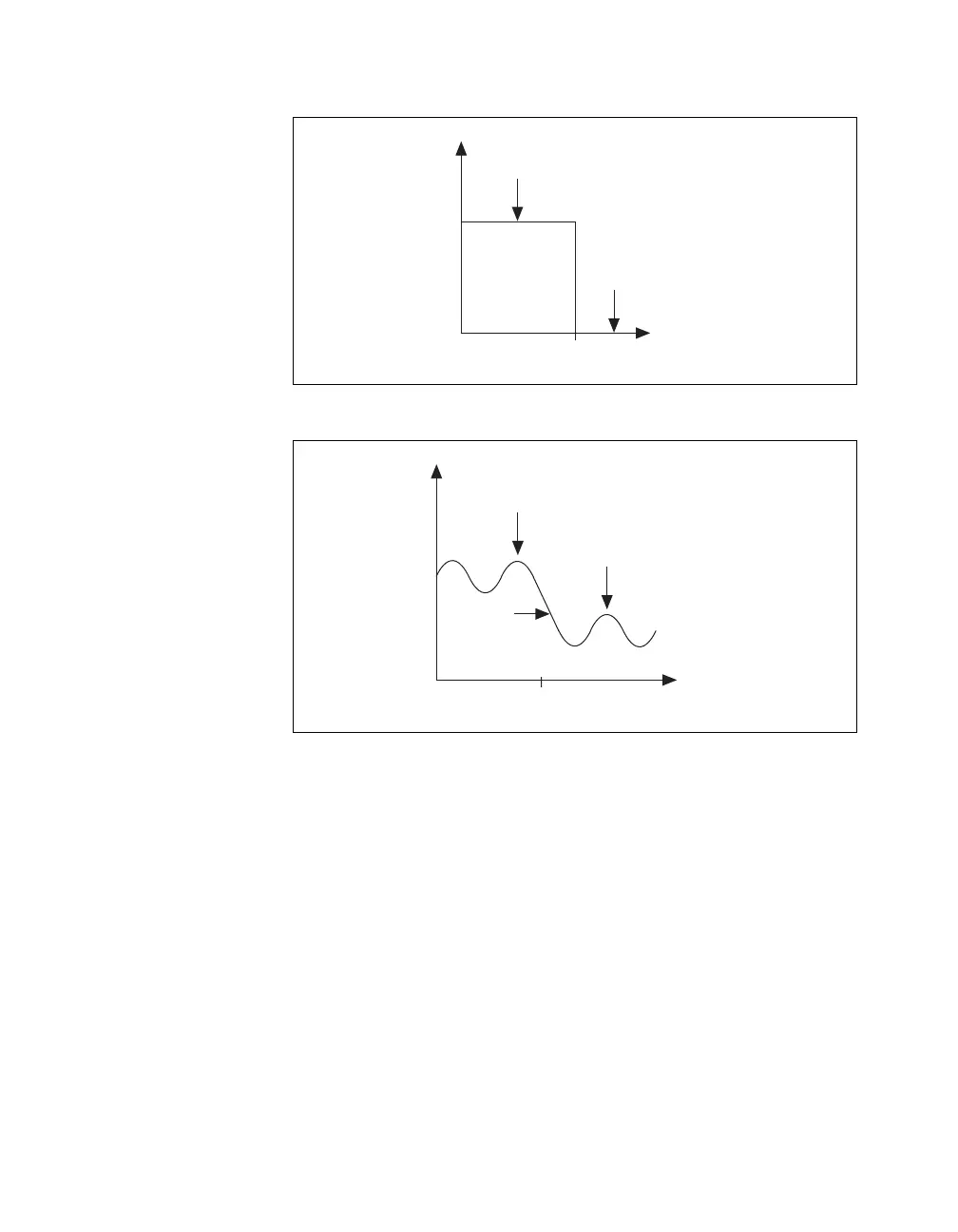
Figure 5-7. Transfer Function Attenuation for a Real Filter
The cut-off frequency, f
c
, is defined as the frequency beyond which the gain
drops 3 dB. Figure 5-6 shows how an ideal filter causes the gain to drop to
zero for all frequencies greater than f
c
. Thus, f
c
does not pass through the
filter to its output. Instead of having a gain of absolute zero for frequencies
greater than f
c
, the real filter has a transition region between the passband
and the stopband, a ripple in the passband, and a stopband with a finite
attenuation gain.
Real filters have some nonlinearity in their phase response, causing signals
at higher frequencies to be delayed by longer times than signals at lower
frequencies and resulting in an overall shape distortion of the signal.
For example, when the square wave shown in Figure 5-8 enters a filter, an
ideal filter smooths the edges of the input, whereas a real filter causes some
Passband
Stopband
Log Frequency
Gain
f
c
Passband
Stopband
Log Frequency
Gain
f
c
Transition
Region
 Loading...