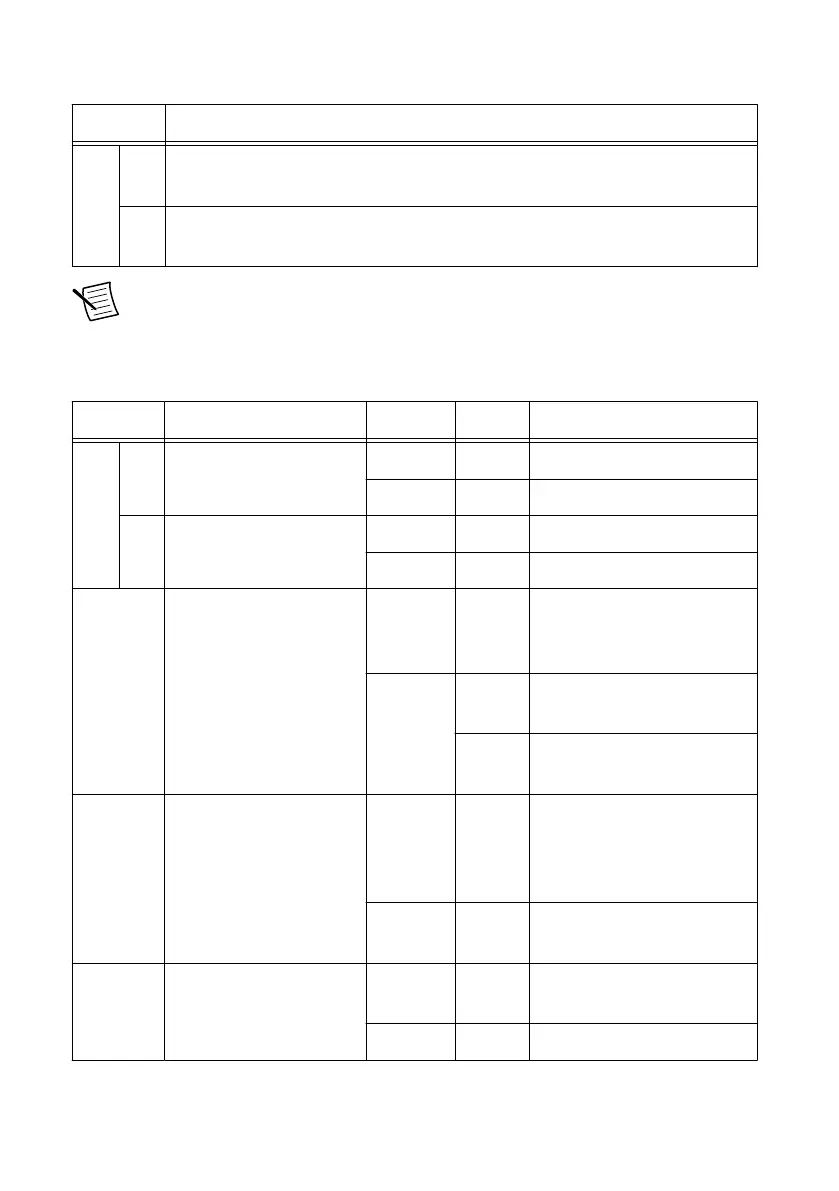
Table 14. Connector Descriptions (Continued)
Connector Use
RF 1 RX1 Input terminal for the RF signal. RX1 is an SMA (f) connector with an
impedance of 50 Ω and is a single-ended input channel.
RX2 Input terminal for the RF signal. RX2 is an SMA (f) connector with an
impedance of 50 Ω and is a single-ended input channel.
Note The LED indications described in the following table occur only when you
use the NI-USRP API with the default API image. When you use LabVIEW FPGA,
you customize the LED indications.
Table 15. LED Indicators
LED Description Color State Indication
RF 0 RX1 Indicates the receive
status of the module.
OFF — The module is not receiving.
Green Solid The module is receiving data.
RX2 Indicates the receive
status of the module.
OFF — The module is not receiving.
Green Solid The module is receiving.
REF Indicates the status of the
reference signal.
OFF — There is no reference signal,
or the device is not locked to
the reference signal.
Green Blinking The device is not locked to
the reference signal.
Solid The device is locked to the
reference signal.
PPS Indicates the pulse per
second (PPS).
OFF — There is no PPS timing
reference signal, or the
device is not locked to the
reference signal.
Green Blinking The device is locked to the
PPS timing reference signal.
GPS Indicates whether the
GPSDO is locked.
OFF — There is no GPSDO or the
GPSDO is not locked.
Green Solid The GPSDO is locked.
USRP-2950/2952/2953/2954/2955 Getting Started Guide | © National Instruments | 31
 Loading...