Table 15. LED Indicators (Continued)
LED Description Color State Indication
LINK Indicates the status of the
link to a host computer.
OFF — There is no link to a host
computer.
Green,
yellow, or
red
Solid The host is actively
communicating with the
device.
RF 1 RX1 Indicates the receive
status of the module.
OFF — The module is not active.
Green Solid The module is receiving data.
RX2 Indicates the receive
status of the module.
OFF — The module is not receiving.
Green Solid The module is receiving.
Back Panel
0 1
PWR
1G/10G ETH
9-16V DC
7.5 A MAX
SFP+Ports
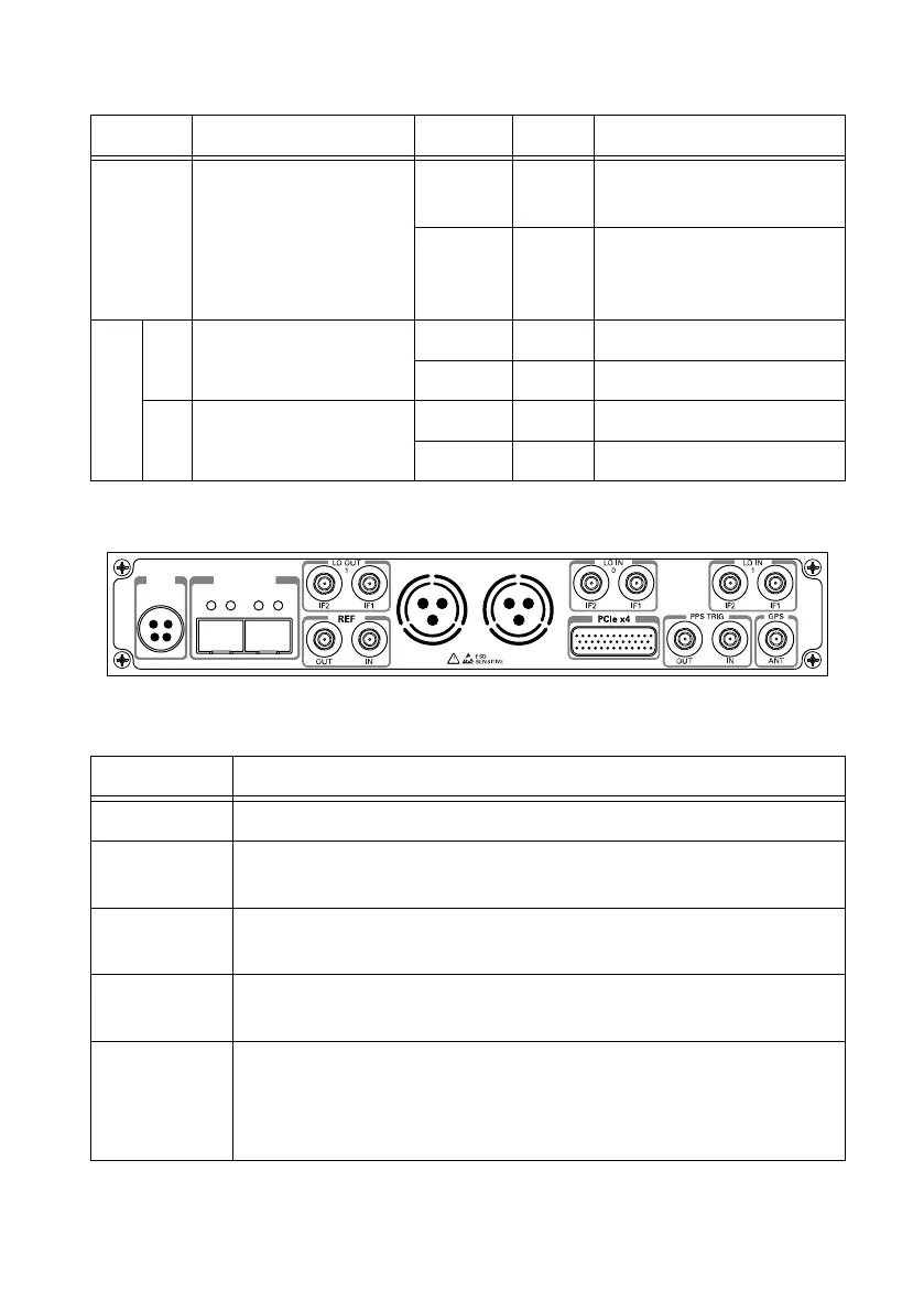
Table 16. Connector Descriptions
Connector Use
PWR Input that accepts a 9 V to 16 V, 6 A external DC power connector.
1G/10G ETH Two SFP+ input terminals used for 1G ETH or 10G ETH connectivity with
the host driver. Not currently supported in LabVIEW FPGA.
LO OUT 1 IF2 Output terminal for the IF LO signal exported by RF 1. LO OUT 1 IF2 is a
female SMA connector with an impedance of 50 Ω.
LO OUT 1 IF1 Output terminal for the RF LO signal exported by RF 1. LO OUT 1 IF1 is
a female SMA connector with an impedance of 50 Ω.
REF OUT Output terminal for an external reference signal for the LO on the device.
REF OUT is a female SMA connector with an impedance of 50 Ω, and it is
a single-ended reference output. The output signal at this connector is
10 MHz at 3.3 V.
32 | ni.com | USRP-2950/2952/2953/2954/2955 Getting Started Guide
 Loading...