NV5/NV3.5 Troubleshooting Manual Responding to alarms
Page 1-36 Issue 3.2 2014-12-10
PA Biasing Procedure
This procedure describes how to enter the bias data for a replacement PA PWB and store it in the RF
power module's EEPROM using the controller debug port and menu. Bias data will be provided on a
tag attached to the replacement PA PWB. To perform this procedure you will need:
– PC with a serial port or terminal program (e.g., Hyperterminal or Tera Term)
– Serial cable with a male DB9 connector and suitable PC serial port connector
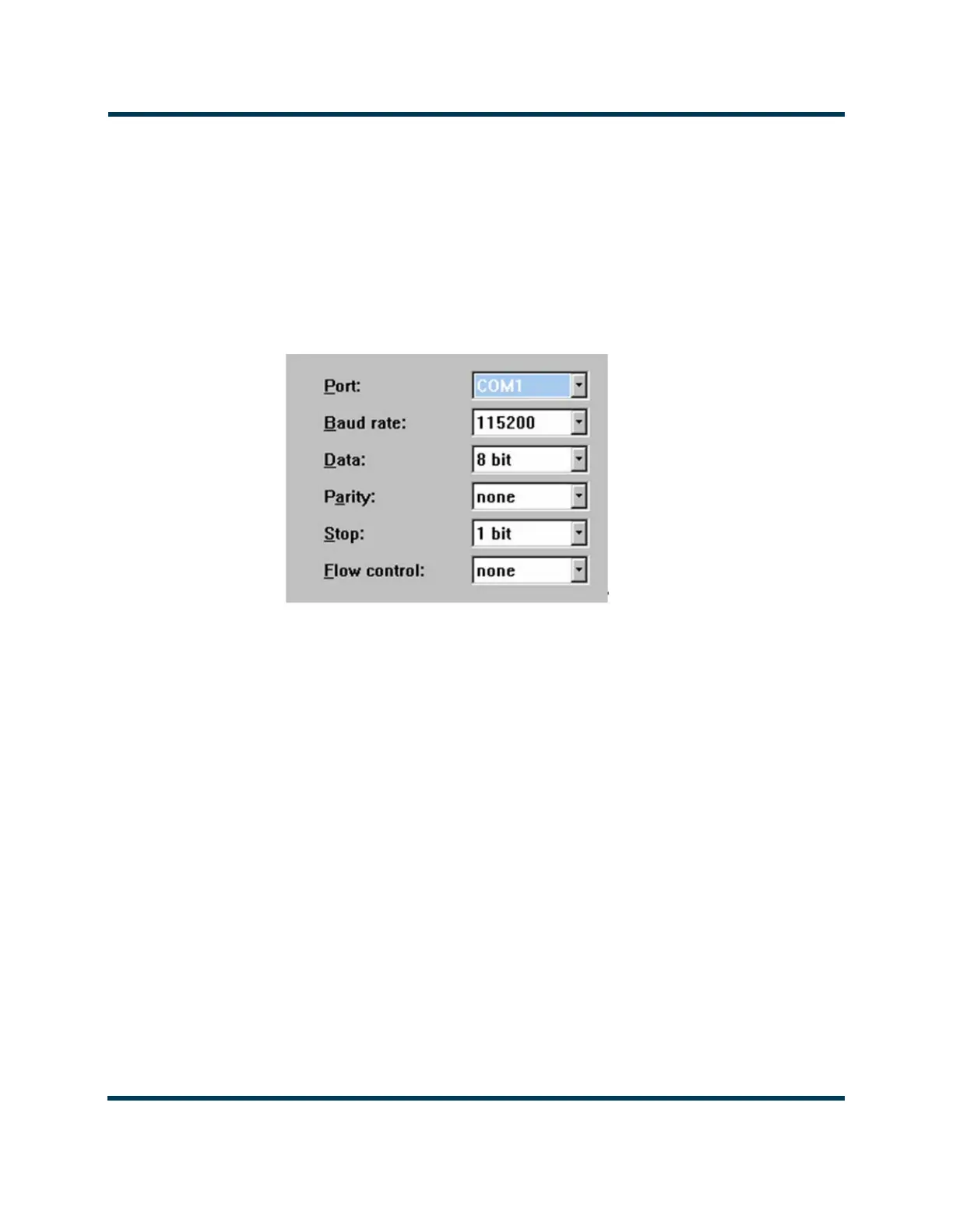
Figure 1.5: Serial Port Setup
1. With the RF power module installed in the transmitter, set the switch on the front of the RF
power module to its ‘down’ position. The module’s lamp should be red.
2. Determine the RF power module address from the module’s position in the transmitter
cabinet. The modules are identified left to right (see Figure 1.3 on page 1-30) with
corresponding addresses of 16 and 17 (0x10H and 0x11H). For example, module 2 is
identified as 0x11H. The PAs within each RF power module are identified as 1 through 8
with corresponding addresses 0 through 7 respectively. The IPA PA’s address is 8.
3. Run the terminal program. Set up the available serial port on the PC with settings as
indicated in Figure 1.5. Substitute your available COM# port for COM1, as necessary.
4. Connect the serial cable between the PC and J18 (Debug RS-232) on the control interface
PWB (NAPC156). Type "Enter debug mode now" and press Enter to view the following
debug menu: