15
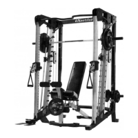
Nautilus NS300X
62
62
44
11
49
45
2" L
2" L
62
45
2 3/4"L
3" L
2" L
25
62
59
78
73
59
78
66
71
2 3/4"L
2" L
45
228.75 ” ( 5810mm)
A
B
D
C
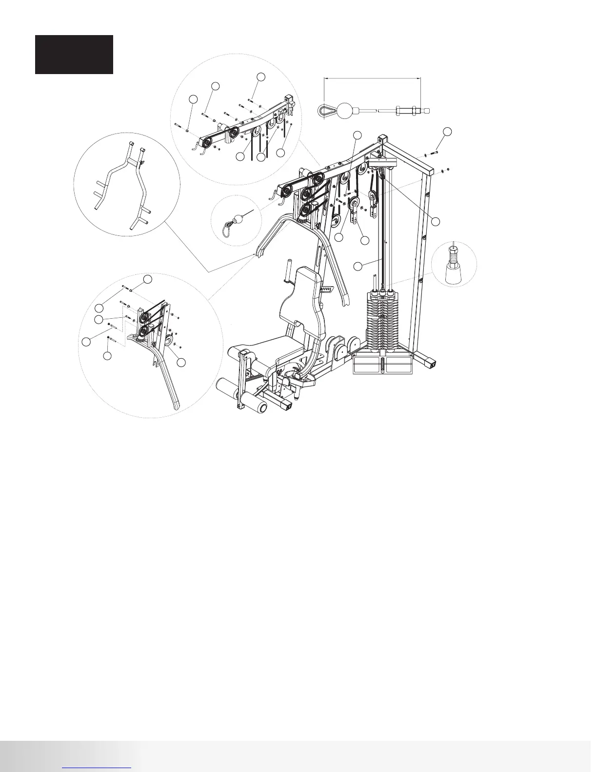
NS300X Press Arm
Step 7 Components:
Procedure:
ASSEMBLY
STEP 7
# Component Qty
A. Thread one end of Cable #2 (49) into the Selector Rod/Top Plate Assembly as shown in Detail A. Do not tighten
locking nut.
B. Draw Cable #2 (49) over a 4 ½” Pulley (45) and place it in the Floating Pulley Bracket (11) making sure that the lower
section of the Floating Pulley Bracket (11) is located between the Guide Rods. Attach Pulley to Bracket using
hardware shown. Tighten hardware securely.
C. Loop Cable #2 (49) around a 4 ½” Pulley (45) and place it in a Double Floating Pulley Bracket (44).
Attach Pulley to inner hole using the hardware shown. Tighten hardware securely.
D. Draw Cable #2 (49) around two 4 ½” Pulleys (45) and place them in the brackets shown in Detail B.
Attach the Pulleys using hardware shown. Tighten hardware securely.
E. Repeat Step C using a second Double Floating Pulley Bracket (44).
F. Loop Cable #2 (49) around a 4 1/2” Pulley (45) and place it in the bracket shown in Detail B.
Attach the Pulley using hardware shown. Tighten hardware securely.
G. Loop Cable #2 (49) around a 4 1/2” Pulley (45) and place it in the bracket shown in Detail C.
Attach the Pulley using hardware shown. Tighten hardware securely.
H. Draw Cable #2 (49) around a 4 ½” Pulley (45) and place it in the slot above the pulley bracket on the
Front Upright Frame. Attach Pulley using the hardware shown in Detail C. Tighten hardware securely.
I. Loop Cable #2 (49) around a 4 ½” Pulley (45) and place it in Press Arm Support Assembly. Attach
Pulley using the lower hole using hardware shown in Detail C. Tighten hardware securely.
J. Loop Cable #2 (49) around a 4 ½” Pulley (45) and place it in the upper slot of the Front Upright
Frame. Attach Pulley using hardware shown in Detail C. Tighten hardware securely.
K. Repeat Step I attaching the Pulley (45) to the upper hole.
L. Loop Cable #2 (49) around a 4 ½” Pulley (45) and place it in the Top Frame. Attach Pulley using
hardware shown in Detail B. Tighten hardware securely. Note: Leave end of Cable #2 inside the Top Frame tube.
M. Feed Cable #2 (49) through the Top Frame tube and out the front slot. Draw Cable around a 4 ½”
Pulley (45). Attach Pulley in front slot using hardware shown in Detail B. Tighten hardware securely.
N. Attach Snap Caps (25) in Press Arm Support Assembly as shown.
25
44
45
49
59
62
66
71
73
78
Snap Cap - Large
Double Floating Pulley Bracket
4 1/2” Pulley
Cable #2 - Pull Down (228.75”)
Hex Bolt 3/8” x 2 3/4”L
Hex Bolt 3/8” x 2”L
Cap Head Allen Screw 3”L
3/8” Flat Washer
3/8” Lock Nut
Step Spacer - 5/8”H
2
2
13
1
4
7
2
14
11
8