34
Note: Your machine may not match the image. For reference only.
To remove the Main Shrouds, start at Step 1. To remove only the Rear
Shrouds, go to Step 11.
1. <RXUPDFKLQHKDVRQHRIWKHVH&UDQNFRQ¿JXUDWLRQV3OHDVHXVHWKHLP-
DJHVWRVHOHFW\RXUFRQ¿JXUDWLRQ
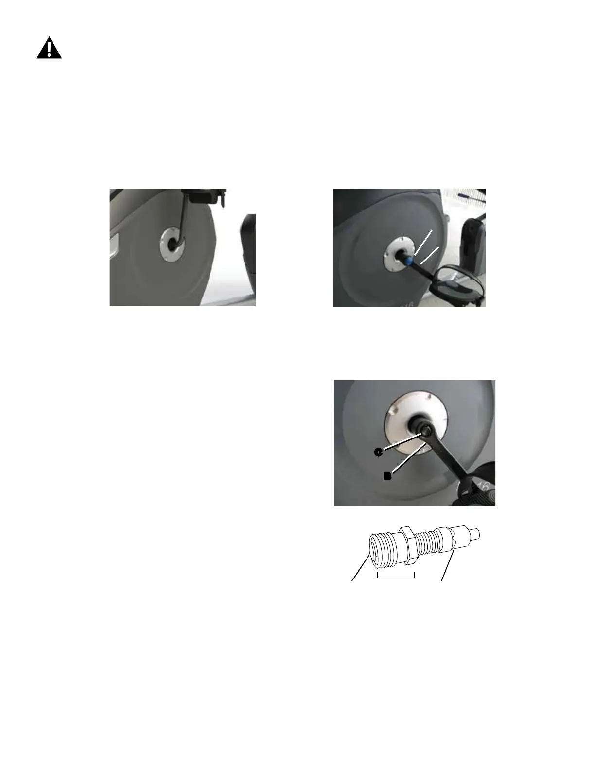
2. Using a wrench and socket, remove the Hex Head Bolt (C).
3. Thread the Crank Puller into the Crank Arm (B). When the Crank Puller is
in the correct position, only 1-2 threads on the outer portion (CP2) of the Crank
Puller should show.
Note: %HVXUHWKHHQGRIWKH%ROW&3RIWKH&UDQN3XOOHULVÀXVKZLWK
the Nut (CP2) as shown, before use.
4. Using a wrench, turn the inner portion (CP3) of the Crank Puller clockwise.
The Crank Arm (C) will slide off as it is tightened.
Go to Step 7.
Disconnect all power to the machine before you service it.
CP1 CP2 CP3
1-Piece Crank:
Go to Step 5.
3-Piece Crank:
8VLQJDÀDWKHDGVFUHZGULYHUUHPRYHWKHWKUHDGHG&DS$IURP
the Crank Arm (B) to expose the Hex Head Bolt (C). Continue to
Step 2.
$
B
C
B
 Loading...