46
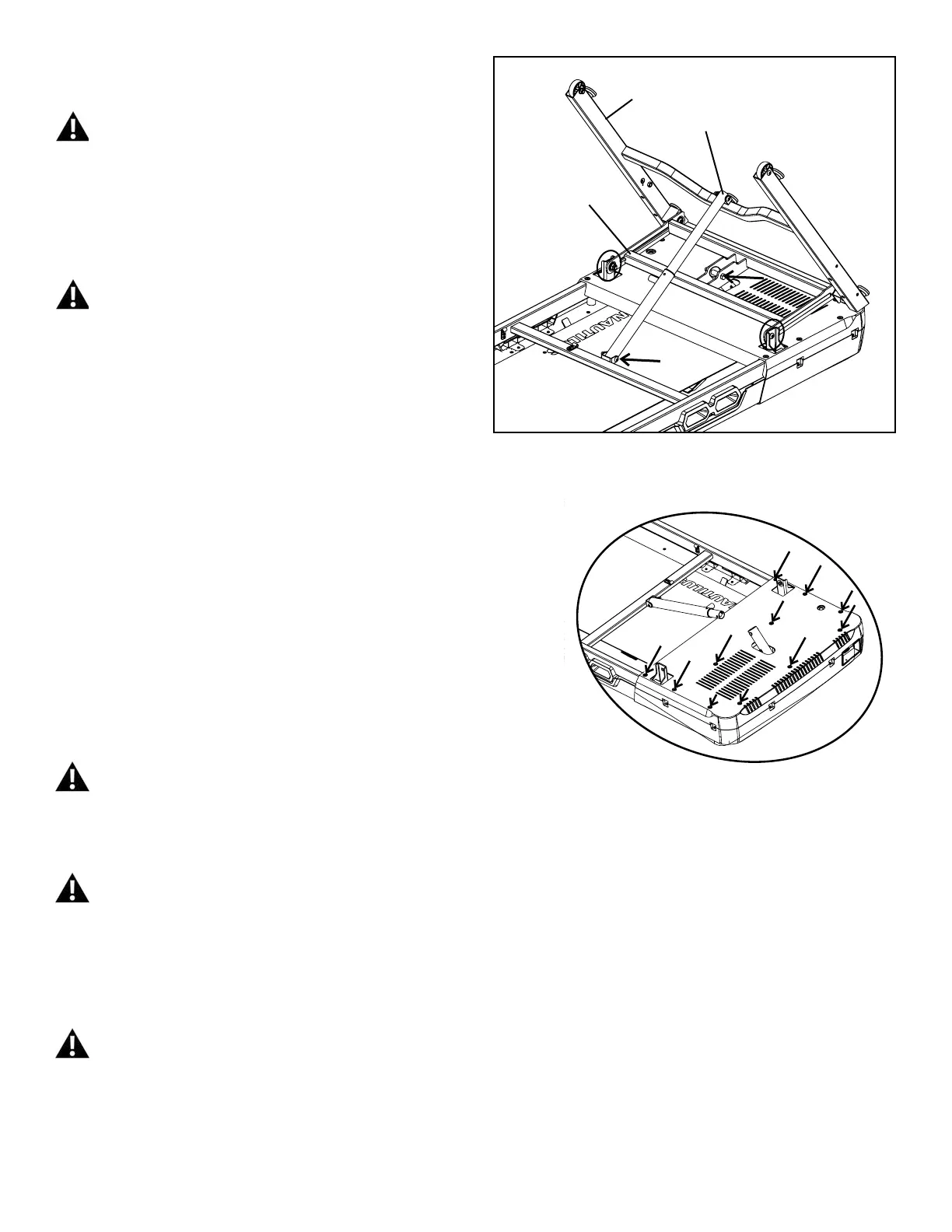
17.Usinga13mmwrenchanda6mmhexwrench,removethe2screws
(indicated with ovals) from the Incline and Base Frame Weldments.
Be aware that when the Hardware is released from the
Weldments, they may abruptly move. Be sure to keep clear of
any potential pinch opportunities.
18.Usinga13mmwrenchanda6mmhexwrench,removetheindicated
hardware (with arrows) from the Incline Motor Assembly and the Lifting
Shock.
Be aware that when the Lift Shock is released from the Base
Frame Weldment, the Weldment may abruptly move and pivot
downward. Be sure to keep clear of any potential pinch
opportunities from this motion.
19. Using a #2 Phillips screwdriver, remove the 11 indicated screws from
the Bottom Motor Cover. Remove the old Bottom Motor Cover.
20. Place the new Bottom Motor Cover onto the Deck Frame and attach it
using a #2 Phillips screwdriver.
21.Usinga13mmwrenchanda6mmhexwrench,re-attachtheIncline
and Base Frame Weldments to the Deck Frame.
Be sure to keep clear of any potential pinch opportunities.
22.Usinga13mmwrenchanda6mmhexwrench,re-attachtheIncline
Motor Assembly and the Lifting Shock.
Be sure to keep clear of any potential pinch opportunities.
23.Withtheassistanceofatleastasecondperson,iptheBaseAs-
sembly to the Upright position. Be aware that the Lifting Shock will begin
to compress when placed back to an upright position, lowering the Base
Assembly.
Be sure the area is clear around the Base Assembly before
ipping it. Do not grasp the Walking Belt since it can abruptly
move.
Base Frame Weldment
Lift Shock
Incline Weldment

 Loading...