SECTION5–MAINTENANCESCHEDULEANDSERVICEPROCEDURES
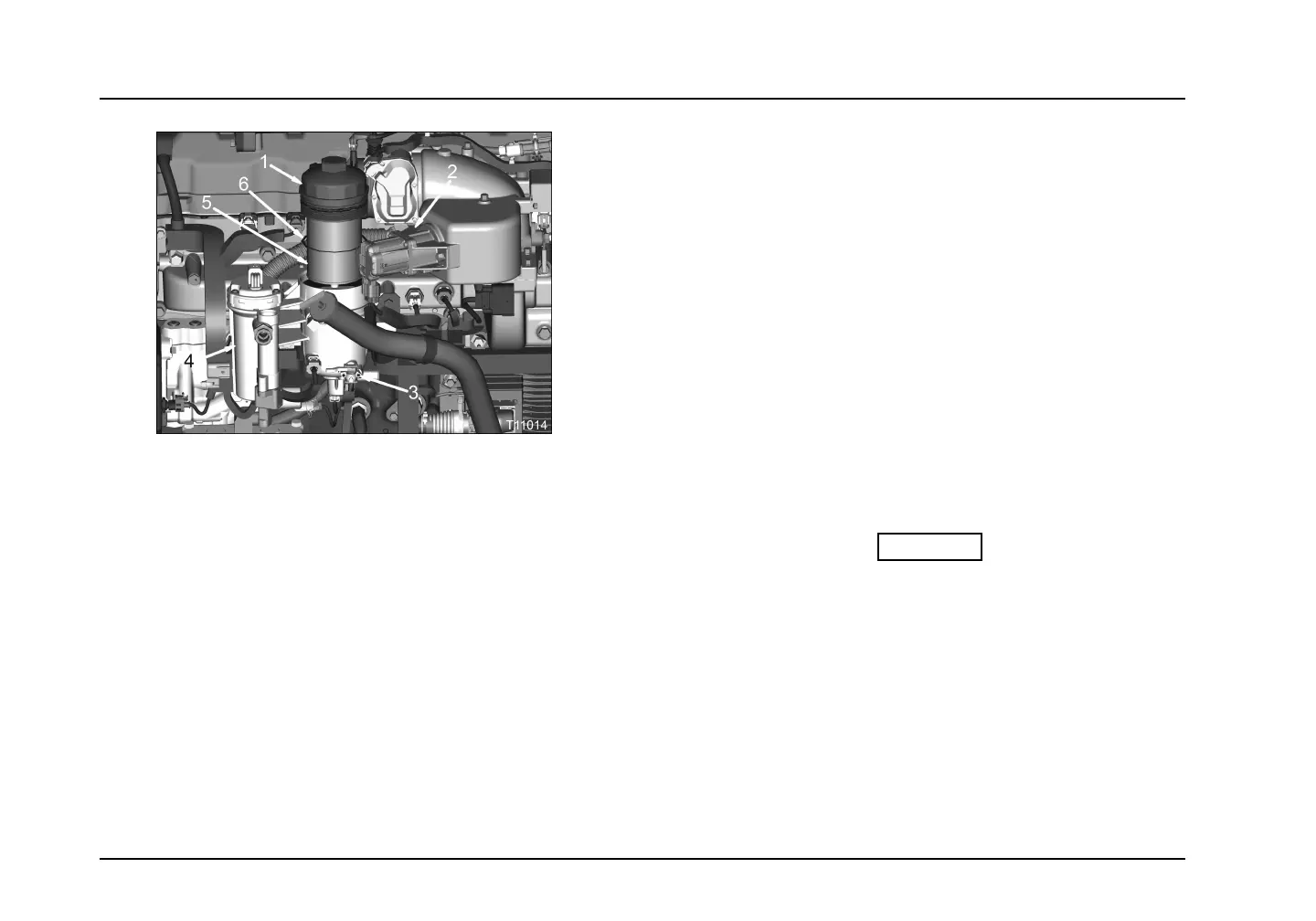
Figure38Fuellterremovalandinstallation
1.Fuelltercover
2.ExhaustGasRecirculation(EGR)valve
3.Waterdrainvalve
4.Fuelpump(fuelstrainerlocation)
5.Fuellterelement
6.FuelltercoverO-ring
10.Continueturningthefuelltercoveruntilloose.Removethe
fuelltercoverandelementfromthefuellterhousing.
11.Removethefuelltercoverfromthefuellterelementby
holdingtheelementverticallyandpushinguponthecover.
Thecoverwillsnapoffthefuellterelement.Disposeofthe
fuellterelementaccordingtoapplicableregulations.
12.RemoveO-ringfromthefuelltercover.DiscardO-ring.
13.CoatanewfuellterO-ringforthefuelltercoverwithclean
dieselfuelandinstallontothefuelltercover.
14.Attachfuelltercovertothefuellterelement.Securethe
fuelltercovertothefuellterelementbypushingthefuel
ltercoverontothefuellterelement.Thefuelltercover
willsnapontothefuellterelement.
15.Coatthreadsoffuelltercoverwithcleandieselfuel.
16.Installafuellterelementwithcoverintothefuellter
housing.Slowlylowerthefuellterelementintothefuel
lterhousing,untilfuelltercoverisreadytobesecuredto
thefuellterhousing.
17.Securethefuelltercoverandelementtothefuellter
housingbyturningthefuelltercoverclockwiseuntil
nger-tight.
CAUTION
Topreventenginedamage,tightenfuelcoveron
fuellterassembly.
18.Usinga23mmwrenchtightenfuelltercoverto30N·m(22
lbf·ft).
19.Depressclutchpedalifequipped.
20.TurntheignitionswitchtoONforapproximately60seconds,
allowingthefuelpumptoprimethefuelsystem.SeePriming
theFuelSystem(page46).
Page78
 Loading...


