SECTION 1 – ENGINE SYSTEMS
Engine Component Locations
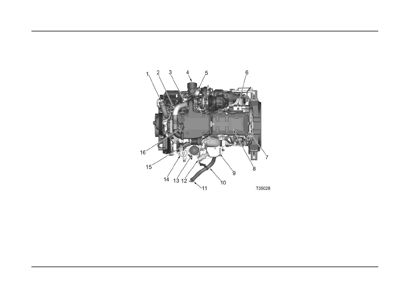
COMPONENT LOCATION - TOP
Figure 3 Top
1. Water outlet tube assembly
2. Interstage cooler inlet duct (245 HP and
above)
3. Interstage cooler (245 HP and above)
4. Turbocharger air inlet duct
5. H igh-pressure turbocharger outlet
6. Exhaust brake valve assembly
7. Valve cover
8. Exhaust emission label ( location)
9. Air and Exha ust Gas Recircula tion (EGR)
mixer duct
10. Oil filler tube
11. Oil level gauge
12. EGR valve
13. Fuel filter assembly
14. Electronic fuel pump (fuel strainer
location)
15. Throttle coupling
16. Deaeration hose elbow
Form No. 1172040R1
Page 24
Printed in the United States of America
 Loading...


