-29-
Service Manual CP-785F
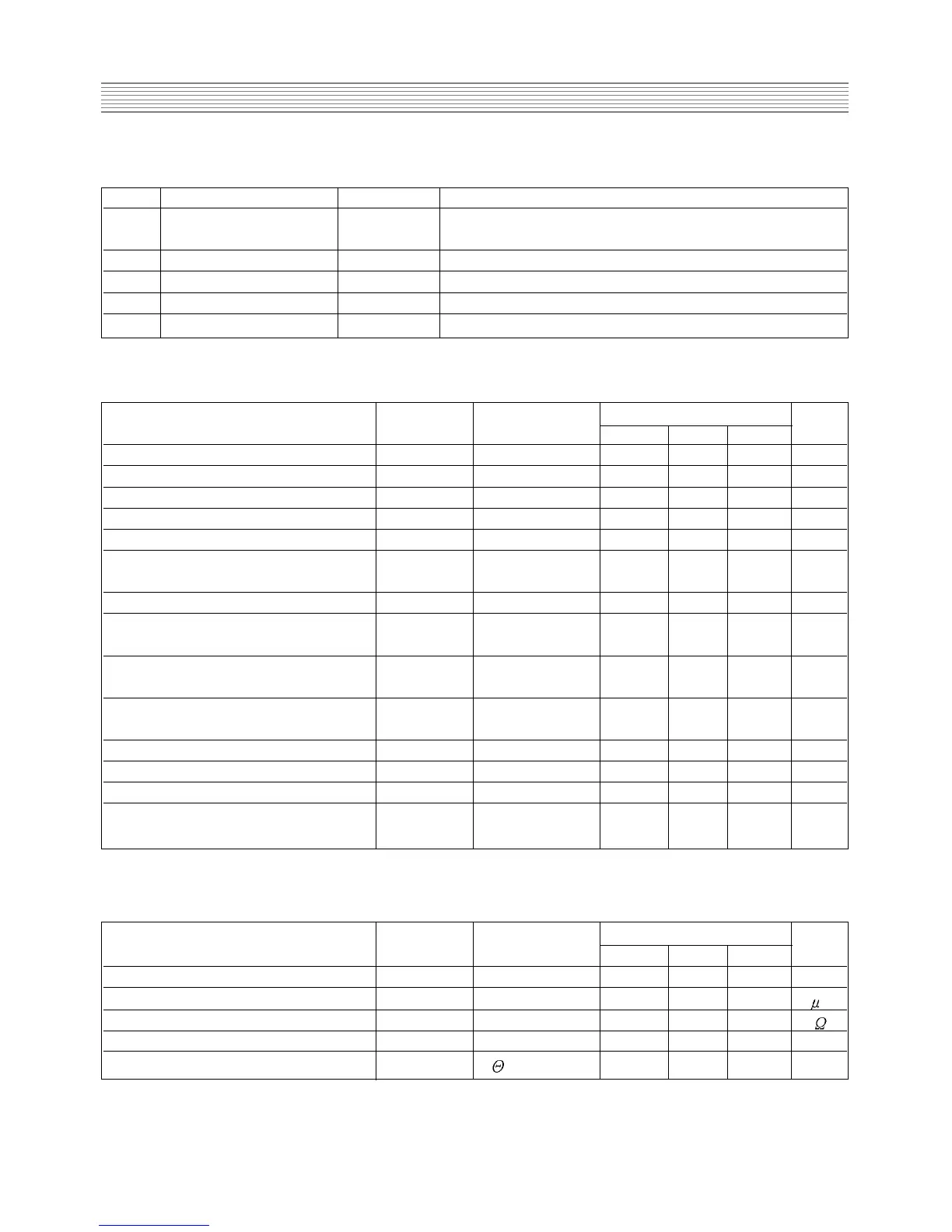
4-7-4 Pins description
pin name symbol description
1 Overcurrent / feedback O.C.P./ F.B. Input of overcurrent detection signal and
feedback signal
2 Source S MOSFET source
3 Drain D MOSFET drain
4 Supply V
IN Input of power supply for control circuit
5 Ground GND Ground
4-7-5 Control part electrical characteristics
IC pins symbol rating unit
description
number min. typ. max.
Operation start voltage 4-5 VIN (on) 14.4 16 17.6 V
Operation stop voltage 4-5 VIN (off) 9 10 11 V
Circuit current in operation 4-5 IIN (on) - - 30 mA
Circuit current in non-operation 4-5 I
IN
(off) - - 100 A
Maximum OFF time - TOFF (max) 45 - 55 sec
Minimum time for input of quaxi 1-5 TTH (2) - - 1.0 sec
resonant signals
Minimum off time - T
OFF (min) - - 1.5 sec
O.C.P./F.B. terminal threshold 1-5 VTH (1) 0.68 0.73 0.78 V
voltage 1
O.C.P./F.B. terminal threshold 1-5 VTH (2) 1.3 1.45 1.6 V
voltage 2
O.C.P./F.B. terminal extraction 1-2 I
OCP/FB 1.2 1.35 1.5 mA
current
O.V.P. operation voltage 4-5 V
IN (OVP) 20.5 22.5 24.5 V
Latch circuit sustaining voltage 4-5 IIN (H) - - 400 A
Latch circuit release voltage 4-5 VIN (La.off) 6.6 - 8.4 V
Thermal shutdown operating - TJ (TSD) 140 - -
0
C
temperature
IC pins symbol rating unit
description
number min. typ. max.
Drain-to-source breakdown voltage 3-2 VDSS 650 - - V
Drain leakage current 3-2 I
DSS - - 300
A
On-resistance 3-2 RDS (on) - - 1.15
Switching time 3-2 tf - - 250 nsec
Thermal resistance -
CH -F - - 0.95
o
C/W
4-7-6 MOSFET electrical characteristics