SYSTEM CONFIGURATION GUIDE – NEC Express5800R120f-1E
NEC Corporation Revision 6.0 – July 16, 2015 9
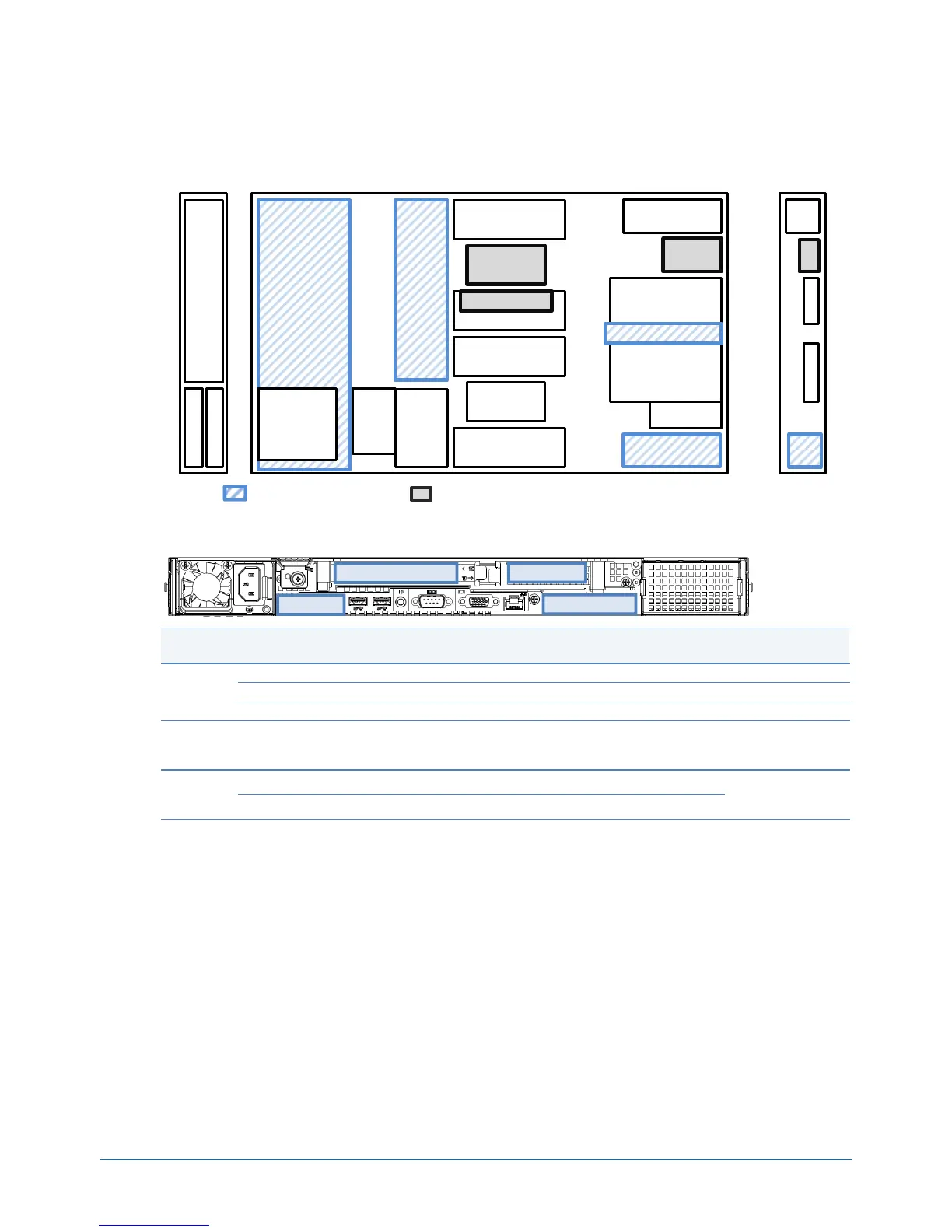
Configuration Diagram
Legend: Standard Components Minimum required components
Expansion Slots
PCIe 3.0 x8, x8 connector, for a dedicated RAID controller
PCIe 3.0 x8, x8 connector, for a dedicated LOM Card
PCIe 3.0 x8, x8 connector, Low-profile, up to 220 mm length
PCIe 3.0 x8, x8 connector, Full-height, up to 220 mm length
PCIe 3.0 x16, x16 connector, Full-height, up to 220 mm length
Required 2 CPU,
Optional Riser
PCIe 3.0 x16, x16 connector, Low-profile, up to 220/312 mm length
Optical Drive Bay
2.5-inch
Hot Plug
Drive Cage
CPU 2
4x DIMM Slots
4x DIMM Slots
4x DIMM Slots
4x DIMM Slots
Hot Plug
Power Supply 2
RAID Slot
PCIe 3.0
PCIe 3.0
2x RAID
FBU Slots
PCI Riser
Cooling Fan
1xDIMM
Cooling
Fan
(CPU2)
Hot Plug
Power Supply 1
LOM
Card
CPU 1
6x 2.5-inch
Drives
2x 2.5-inch Drives
PSU
2
PSU
1
#1C #1D
LOM
Optical
Driver
Bay
CHASSIS
FRONT
CHASSIS
INSIDE
CHASSIS
REAR

 Loading...

