EasyManua.ls Logo

NEC MultiSync LCD1920NX User Manual

NEC MultiSync LCD1920NX
178 pages
To Next Page IconTo Next Page
To Previous Page IconTo Previous Page
Page #29 background image
1-26
TCO’95
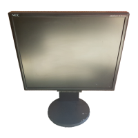
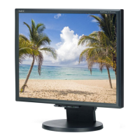
MultiSync LCD1920NX Black Model
Congratulations! You have just purchased a TCO’95
approved and labeled product! Your choice has
provided you with a product developed for
professional use. Your purchase has also contributed
to reducing the burden on the environment and also,
to the further development of environmentally
adapted electronics products.
Why do we have environmentally labelled computers?
In many countries, environmental labelling has become an
established method for encouraging the adaptation of goods and
services to the environment. The main problem, as far as
computers and other electronics equipment are concerned, is that
environmentally harmful substances are used both in the products
and during the manufacturing. Since it has not been possible for
the majority of electronics equipment to be recycled in a
satisfactory way, most of these potentially damaging substances
sooner or later enter Nature.
There are also other characteristics of a computer, such as
energy consumption levels, that are important from the viewpoints
of both the work (Internal) and natural (external) environments.
Since all methods of conventional electricity generation have a
negative effect on the environment (acidic and climate-influencing
emissions, radioactive waste, etc.), it is vital to conserve energy.
Electronics equipment in offices consume an enormous amount
of energy since they are often left running continuously.
What does labelling involve?
This product meets the requirements for the TCO’95 scheme
which provides for international and environmental labelling of
personal computers. The labelling scheme was developed as a
joint effort by the TCO (The Swedish Confederation of
Professional Employees), Naturskyddsforeningen (The Swedish
Society for Nature Conservation) and NUTEK (The National Board
for Industrial and Technical Development in Sweden).
The requirements cover a wide range of issues: environment,
ergonomics, usability, emission of electrical and magnetic fields,
energy consumption and electrical and fire safety.
The environmental demands concern restrictions on the presence
and use of heavy metals, brominated and chlorinated flame
retardants, CFCs (freons) and chlorinated solvents, among other
things. The product must be prepared for recycling and the
manufacturer is obliged to have an environmental plan which must
be adhered to in each country where the company implements its
operational policy. The energy requirements include a demand
that the computer and/or display, after a certain period of
inactivity, shall reduce its power consumption to a lower level in
one or more stages. The length of time to reactivate the computer
shall be reasonable for the user.
Labelled products must meet strict environmental demands, for
example, in respect of the reduction of electric and magnetic
fields, physical and visual ergonomics and good usability.
TCO’95 is a co-operative project between TCO (The Swedish
Confederation of Professional Employees),
Naturskyddsforeningen (The Swedish Society for Nature
Conservation) and NUTEK (The National Board for Industrial and
Technical Development in Sweden).
Environmental Requirements
Brominated flame retardants
Brominated flame retardants are present in printed circuit boards,
cables, wires, casings and housings. In turn, they delay the
spread of fire. Up to thirty percent of the plastic in a computer
casing can consist of flame retardant substances. These are
related to another group of environmental toxins, PCBs, which are
suspected to give rise to similar harm, including reproductive
damage in fisheating birds and mammals, due to the bio-
accumulative* processes. Flame retardants have been found in
human blood and researchers fear that disturbances in foetus
development may occur.
TCO’95 demand requires that plastic components weighing more
than 25 grams must not contain organically bound chlorine and
bromine.
Lead**
Lead can be found in picture tubes, display screens, solders and
capacitors. Lead damages the nervous system and in higher
doses, causes lead poisoning.
TCO’95 requirement permits the inclusion of lead since no
replacement has yet been developed.
Cadmium**
Cadmium is present in rechargeable batteries and in the
colourgenerating layers of certain computer displays. Cadmium
damages the nervous system and is toxic in high doses.
TCO’95 requirement states that batteries may not contain more
than 25 ppm (parts per million) of cadmium. The colourgenerating
layers of display screens must not contain any cadmium.
Mercury**
Mercury is sometimes found in batteries, relays, switches, and
back-light systems, Mercury damages the nervous system and is
toxic in high doses.
TCO’95 requirement states that batteries may not contain more
than 25 ppm (parts per million) of mercury. It also demands that
no mercury is present in any of the electrical or electronics
components concerned with the display unit, except the back-light
system.
CFCs (freons)
CFCs (freons) are sometimes used for washing printed circuit
boards and in the manufacturing of expanded foam for packaging.
CFCs break down ozone and thereby damage the ozone layer in
the stratosphere, causing increased reception on Earth of
ultraviolet light with consequent increased risks of skin cancer
(malignant melanoma).
The relevant TCO’95 requirement; Neither CFCs nor HCFCs may
be used during the manufacturing of the product or its packaging.
*Bio-accumulative is defined as substances which accumulate
within living organisms.
**Lead, Cadmium and Mercury are heavy metals which are
Bio-accumulative.
To obtain complete information on the environmental criteria
document, order from:
TCO Development Unit
SE-114 94 Stockholm
SWEDEN
FAX Number: +46 8 782 92 07
E-mail (Internet): development@tco.se
You may also obtain current information on TCO’95 approved
and labelled products by visiting their website at:
http://www.tco-info.com/

Table of Contents

Other manuals for NEC MultiSync LCD1920NX

Question and Answer IconNeed help?

Do you have a question about the NEC MultiSync LCD1920NX and is the answer not in the manual?

NEC MultiSync LCD1920NX Specifications

General IconGeneral
Screen Size19 inches
Display TypeLCD
Maximum Resolution1280 x 1024
Aspect Ratio5:4
Brightness250 cd/m²
Contrast Ratio500:1
Response Time25 ms
Input ConnectorsVGA, DVI-D
Panel TypeTN
Power Consumption45 W
Viewing Angles160° (horizontal), 160° (vertical)

Summary

Safety Precautions and Warnings

General Service Warnings

Safety warnings for service personnel regarding training, equipment, and procedures.

Product Safety Cautions

Cautions for servicing, parts replacement, and tool usage.

Getting Started Guide

Unique Product Features

Highlights key features and technologies of the LCD monitor.

Monitor Adjustments

Viewing Angle Adjustments

Instructions on how to tilt and swivel the monitor for optimal viewing.

Quick Installation Procedures

Connecting Monitor Cables

Steps for connecting power, D-SUB, and DVI-D cables for initial setup.

Monitor Operations Guide

Power On/Off Procedures

Instructions on how to turn the monitor on and off using the power button.

Function and Hot Key Usage

Explanation of the monitor's function and hot keys for OSD control.

OSD Main Menu Navigation

Contrast and Brightness Settings

How to adjust screen contrast and brightness using OSD controls.

OSD Main Menu - Advanced Settings

LCD Adjustments and Language Selection

Adjustments for H/V position, H-SIZE, FINE TUNE and OSD language selection.

Automatic Sync and Calibration Functions

Using AUTO-SYNC and related calibration functions within the OSD.

Recommended Use and Ergonomics

General Safety Precautions

Important safety advice for setting up and using the monitor.

Monitor Placement for Eye Strain Reduction

Advice on positioning the monitor to reduce eye and body strain.

Ergonomic Best Practices

Recommendations for optimal ergonomic benefits and eye comfort.

Troubleshooting Common Issues

No Picture or Image Display Problems

Solutions for problems showing no image, persistence, or instability.

LED Indicators and Display Size Issues

Troubleshooting for power LED and improper display sizing issues.

Limited Warranty Information

Warranty Coverage and Exclusions

Explains the warranty period, conditions, and exclusions for product defects.

Declaration of Conformity

FCC and Canadian Regulatory Compliance

Declares conformity with FCC Rules and Canadian regulations.

English Section - Safety and Declarations

General Safety Warnings

Standard warnings regarding fire, shock hazards, and cabinet opening.

Disassembly Procedures - Initial Steps

Disassembly Procedures - Internal Components

Disassembly Procedures - LCD Module

Adjustment Procedures - Basic Operation

Adjustment Procedures - Mode Settings

Factory Mode Operations

Instructions for entering factory mode and checking status.

Adjustment Procedures - Data Writing

Data Writing Process Steps

Step-by-step guide for writing adjustment data using software.

Adjustment Procedures - Input Signal

Inspection Procedures - Set Inspection

Inspection Procedures - Mode Settings

Inspection Procedures - OSD Control

OSD Button Functions Explained

Explains the function of each button for OSD navigation and control.

Inspection Procedures - Power and Brightness

Unit Power On Sequence

Steps for powering on the unit and checking LED status.

Brightness and Contrast Check

Procedure to inspect and verify brightness and contrast adjustments.

Inspection Procedures - Automatic Adjustments

Auto-Sync and Fine Tune Verification

Verifies the functionality of AUTO-SYNC, H-SIZE, and FINE TUNE.

Inspection Procedures - Signal Discrimination

Input Signal Verification Process

Confirms correct display for various input signals and sync types.

Inspection Procedures - Video Detect and Reset

Video Input Detection Testing

Verifies automatic video input port switching and detection.

External LCD Module Inspection

Display Surface Defect Criteria

Lists criteria for visually inspecting the display surface for defects.

External LCD Module Inspection - Defect Standards

External LCD Module Inspection - Surface Imperfections

Inspection - Operational Procedures

PNP.EXE Execution and Key Assignments

Steps for starting PNP.EXE and assigning operation keys.

EDID Data Writing Process

Guide for writing EDID data for D-SUB and DVI-D interfaces.

Inspection - EDID Data File

Troubleshooting - Power System Issues

Power Availability Diagnosis Flowchart

Flowchart for diagnosing power availability issues starting from +12V.

Troubleshooting - No Image Display

Image Display Failure (LED Green, No OSD/Backlight)

Troubleshooting steps when LED is green but no OSD or backlight is active.

Troubleshooting - No OSD or Backlight

Power Supply Checks (+12V, +5V)

Verifies +12V and +5V availability for the inverter and panel.

Troubleshooting - No Image with OSD

Signal Output and IC Checks

Checks for VIDEO/DVI signals, H-sync, and IC outputs.

Troubleshooting - Picture Quality Errors

High-Light Adjustment and Correction

Troubleshooting steps for high-light issues in white or black screens.

Troubleshooting - Image Clarity Issues

H-SIZE and FINE TUNE Troubleshooting

Addresses unclear images after adjusting H-SIZE and FINE TUNE.

Troubleshooting - Image Noise

Noise Reduction and Contrast Adjustment

Steps to reduce image noise by adjusting contrast and checking cables.

Troubleshooting - Other Operational Errors

Backlight Malfunction Troubleshooting

Troubleshooting steps for backlight issues, checking voltages and PCBs.

Troubleshooting - Power Circuit Failures

Power Supply Voltage Verification

Verifies +12V, +5Vx, and VLCD availability for power circuits.

Troubleshooting - Power Circuit Voltage Checks

Voltage Regulation and Stability Checks

Checks specific voltage points (C79, C65, C172) for regulation issues.

System Block Diagram

Overall System Architecture

Illustrates the main functional blocks and signal flow within the monitor.

Analog Signal Input Circuit

A/D Converter Circuit

AM121-2 Dual-Interface Controller

AM121-2 Circuit Diagram

Detailed Circuit Schematic

Detailed schematic diagram of the AM121-2 and its peripheral circuits.

AM121-2 Pinout Description

CPU Pin Description

DDC & IIC Interface

LVDS Interface Circuit

DDC Circuit Description

Power System Circuit Description

Power System Voltage Conversion

Details the power system circuit for converting +12V to +5V and VLCD.

Over Voltage Protection Circuit

Power System Over Voltage Protection

Explains the over-voltage protection mechanism for the power system.

TMDS Signal Process Circuit

TMDS Signal Processing Details

Describes the TMDS signal processing using IC11 and related components.

TMDS Pin Description

Replacement Parts List - ICs and Transistors

Schematic Diagrams - Main Board (1/7)

Power and Control Circuitry

Schematic showing power and control related circuits on the main board.

Schematic Diagrams - Main Board (2/7)

Schematic Diagrams - Main Board (3/7)

Schematic Diagrams - Main Board (4/7)

Schematic Diagrams - Main Board (5/7)

Schematic Diagrams - Main Board (6/7)

Schematic Diagrams - Main Board (7/7)

Related product manuals