English−22
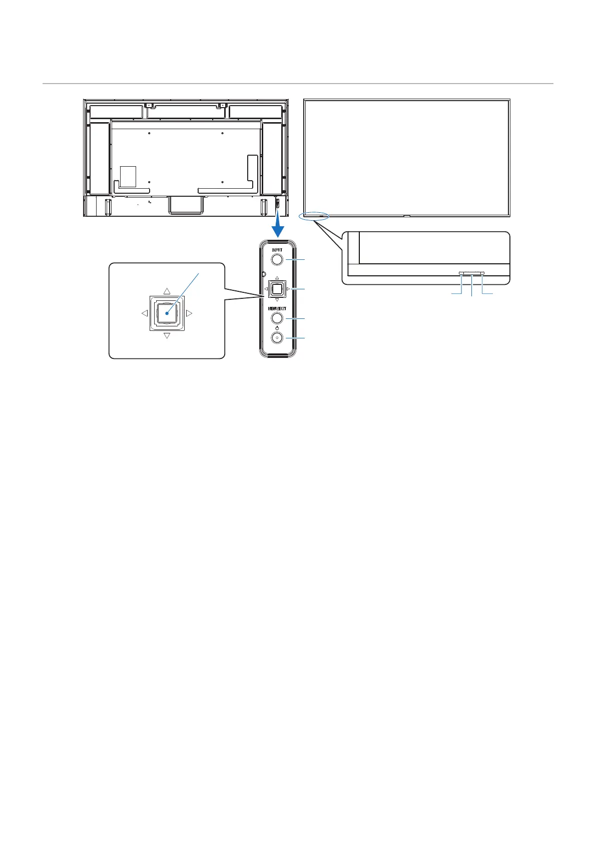
4
3
2
1
6
75
Down
Up
Right
SET
Left
1
⏻
Switches between power on and standby. See page 36.
2
Opens the OSD menu when the OSD menu is closed.
Acts as a back button within the OSD menu to move to the
previous OSD menu.
Acts as an exit button to close the OSD menu when on the
main menu.
3
vw Left/Right control.
• Navigates to the left or right through the OSD Control
menus.
• Increases or decreases adjustments for individual
OSD settings.
• Directly adjusts the VOLUME when the OSD menu is
closed.
sr Up/Down control.
• Navigates up or down through the OSD Control menus.
SET: (button press)
• Selects, or sets the setting for, the highlighted function in
the OSD menu.
*
1
: The v, w, r and s functions change according to the monitor orientation
(landscape/portrait).
4
INPUT: Cycles through the available inputs when the OSD
menu is closed.
[DisplayPort1], [DisplayPort2], [HDMI1], [HDMI2],
[OPTION]*
1
, [COMPUTE MODULE]*
2
. Input names
are shown as their factory preset name.
*
1
: This function depends on which Option Board is installed in the monitor.
*
2
: This input is available when the optional Raspberry Pi Compute Module
Interface Board and Raspberry Pi Compute Module are installed.
See page 84.
5
• Glows blue when the monitor is in active mode*
1
.
• Green and Amber blink alternately when the
[SCHEDULE INFORMATION] function is enabled.
• When a component failure is detected within the monitor,
the indicator will blink red or blink a combination of red
and blue.
• Please refer to the Power ON and OFF Modes table on
page 36.
*
1
: If [OFF] is selected in the [POWER INDICATOR] the LED will not glow
when the monitor is in active mode. See page 107.
6
Receives the signal from the remote control (when using the
wireless remote control). See page 37.
7
Detects the level of ambient light, allowing the monitor
to make automatic adjustments to the backlight setting,
resulting in a more comfortable viewing experience. Do not
cover this sensor. See page 49.