QX-S5500 Series Ethernet Switches
1
(10) Interface module 1 status LED (MOD1)
(11) Interface module 2 status LED (MOD2)
(12) Port status LED mode switching button
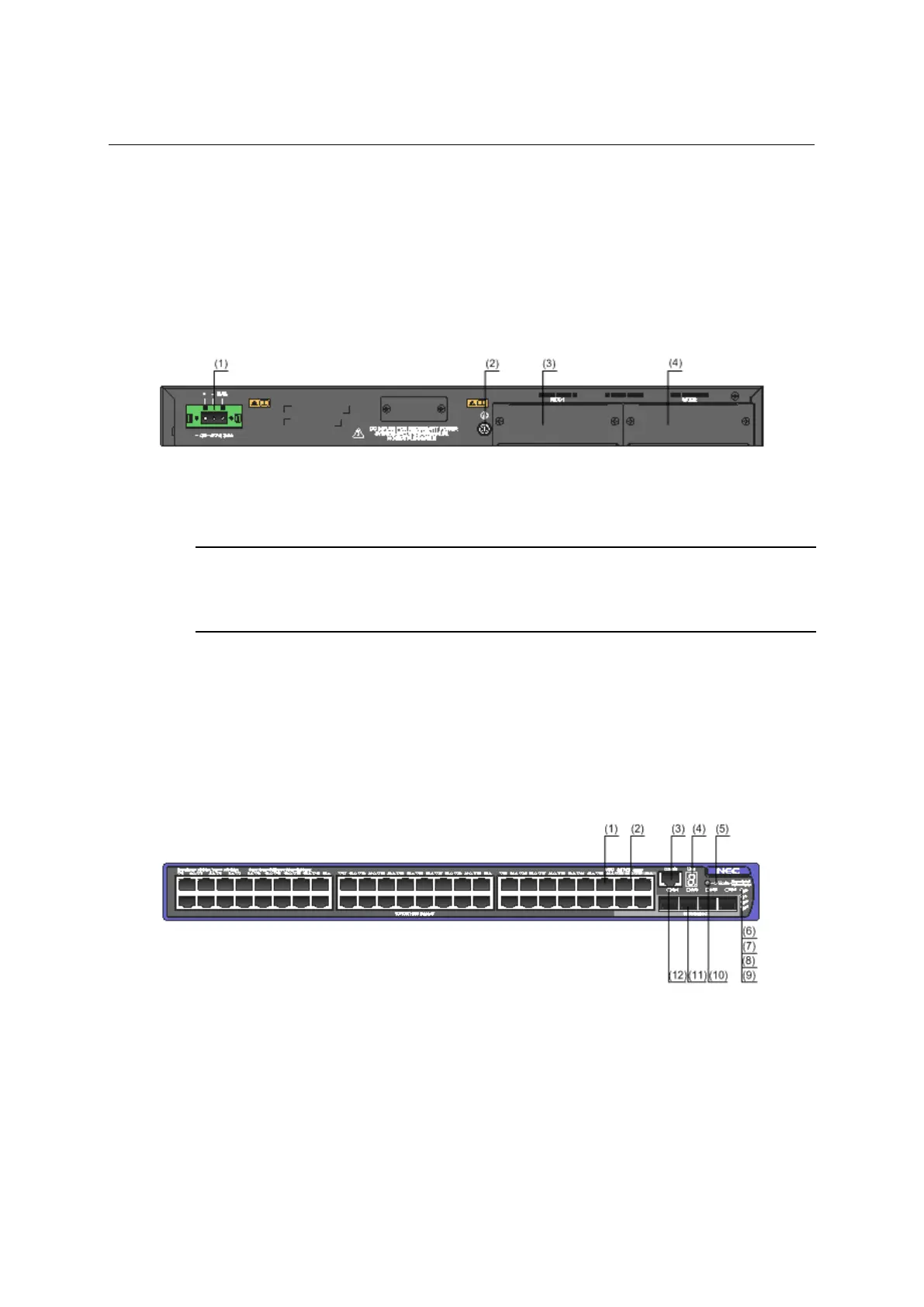
II. Rear panel
Figure 1-4 QX-S5526P-D rear panel
(3) Interface module slot 1 (MOD1)
(4) Interface module slot 2 (MOD2)
NOTE:
Please refer to "Expansion interface module" about a practicable Interface module expansion interface card by
an Interface module slot.
1.2.3 QX-S5550P panel views
I. Front panel
Figure 1-5 QX-S5550P front panel
(1) 10/100/1000BASE-T auto-sensing Ethernet port
(2) 10/100/1000BASE-T auto-sensing Ethernet port status LED
(6) System status LED (PWR)
(8) Interface module 1 status LED (MOD1)
(9) Interface module 2 status LED (MOD2)
(10) Port status LED mode switching button
(11) 100/1000BASE-X SFP port
(12) 100/1000BASE-X SFP port status LED
1-4
 Loading...