Installation Guide
QX-S5500 Series Ethernet Switches
Contents
1 Product overview ........................................................................................................................ 1-1
1.1 Overview ............................................................................................................................ 1-1
1.2 Panel views ........................................................................................................................ 1-2
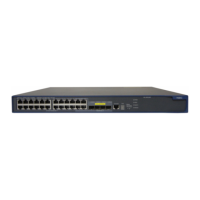
1.2.1 QX-S5526P panel views ......................................................................................... 1-2
1.2.2 QX-S5526P-D panel views ..................................................................................... 1-3
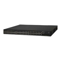
1.2.3 QX-S5550P panel views ......................................................................................... 1-4
1.2.4 QX-S5526T panel views ......................................................................................... 1-5
1.3 Ports ................................................................................................................................... 1-6
1.3.1 Console Port ............................................................................................................ 1-6
1.3.2 10/100/1000BASE-T auto-sensing Ethernet port .................................................... 1-7
1.3.3 SFP port .................................................................................................................. 1-7
1.3.4 Combo Port ............................................................................................................. 1-8
1.4 LED .................................................................................................................................... 1-8
1.4.1 System Status LED ................................................................................................. 1-8
1.4.2 Hot Swappable Power Module Status LEDs ........................................................... 1-9
1.4.3 RPS Status LED ...................................................................................................... 1-9
1.4.4 Port Mode LED ........................................................................................................ 1-9
1.4.5 Seven-Segment LED............................................................................................. 1-10
1.4.6 10/100/1000Base-T Auto-Sensing Ethernet Port Status LED .............................. 1-10
1.4.7 100/1000BASE-X SFP Port Status LED ............................................................... 1-11
1.4.8 Interface Module Status LED ................................................................................ 1-11
1.5 Optional Interface Modules .............................................................................................. 1-12
1.5.1 2-port 10G BASE-CX4 interface module (LS-CX2-T2) ......................................... 1-12
1.5.2 2-port 10G BASE-XFP interface module (LS-SP2-T2) ......................................... 1-13
1.5.3 2-port 10G BASE-XFP interface module (LS-XP2-T2) ......................................... 1-15
1.5.4 1-port 10G BASE-XFP interface module (LS-XP1-T2) ......................................... 1-16
1.5.5 Description of LEDs of Interface Modules ............................................................. 1-16
i
 Loading...