QX-S5500 Series Ethernet Switches
5
Network connection of the switch
in the switch. Connect the plug by which a connector is already the other to a module
of opposite equipment.
3) Confirm that an LED of optical interface is normal. When an LED doesn't light up,
confirm whether the location where a fiber connector is connected (RX/TX) is right.
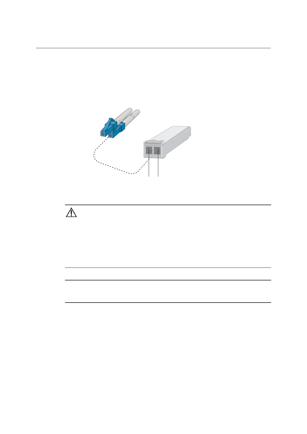
Figure 5-6 Connection of LC optical fiber connector and SFP module
(1) Transmitting side (TX)
CAUTION:
When a connector isn't connected, close a cover of optical interface.
When dust-proof cover is open, or a fiber connector isn't connected to optical interface, don't look at optical
interface directly.
Refer to "preparing for installation" as a notice about a laser.
The sending and receiving direction of data is recorded on SFP/SFP+/XFP module. Please check the
RX/TX position of SFP/SFP+/QSFP+ module by the direction of RX/TX which is ▲ or ↑
. After checking
these, connect a fiber connector appropriately.
NOTE:
Each SFP port belongs to a combo port.
fiber connector
module
5-6
 Loading...