Issue 2.0
SV9100 General Description Manual 5-5
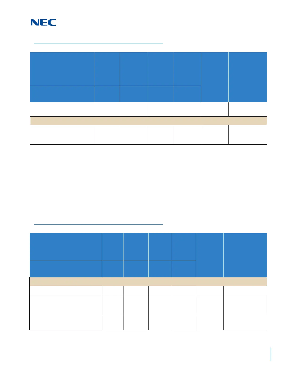
1.2 System Blade Capacities
Table 5-3 SV9100 Maximum 9.5” Gateway and 19” System Capacities – Blades
and Table 5-4 SV9100 Maximum 9.5” Base and Expansion System Capacities –
Blades on page 5-8 show the maximum number for each blade that can be
installed in a system.
This is determined by the maximum blade configuration allowed. When installing
single line sets, DISA, or tie lines, CPU circuits must be allocated for DTMF
receivers. To install single line sets with CO/PBX line access, or when installing
immediate-start tie lines, CPU circuits must be allocated for dial tone detection.
CHS2UG B SMALL BATT BOX
(Small Battery Box)
111450 x (1+3)–
Power Supply:
MPS7101
1 1 1 4 – 1 is factory
installed with
each chassis
Table 5-2 9.5” Base and Expansion Maximum System Capacities – Chassis (Continued)
Hardware 9.5” Base
9.5” Base
+
Expansion
with CPU
9.5” Base
+
Expansion
without
CPU
9.5” Base
+
Expansion
x4
Networked
Chassis
(NetLink)
Comments
Number of Slot(s) for
Interface Package
3 Slots 5 Slots 6 Slots 23 Slots
Table 5-3 SV9100 Maximum 9.5” Gateway and 19” System Capacities – Blades
Hardware
9.5”
Chassis
19”
Chassis
with CPU
19”
Chassis
without
CPU
19”
Chassis
x4
Networked
Chassis
(NetLink)
Comments
Number of Slot(s) for Interface
Package
3 Slots 5 Slots 6 Slots 23 Slots
Common Control Blades:
GCD-CP10
11 01 50 –
GPZ-IPLE
(VoIP Daughter Board)
1 1 0 1 50 This unit provides
256 VOIP Gateway
channels
GCD-SVR2
(Server Blade)
11 11 1

 Loading...


