© by NECTA VENDING SOLUTIONS SpA
26
0102 Colibrì
PRINTED BOARD FUNCTIONS
AND INDICATOR LIGHTS
CONTROL BOARD
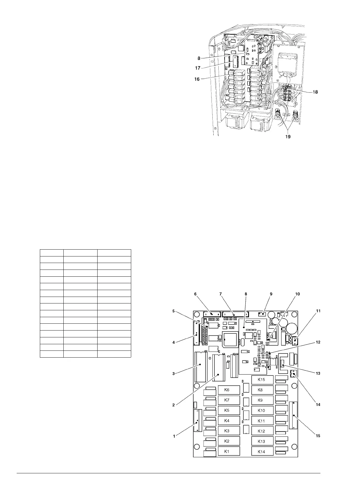
This board, placed at the back of the machine, (see Fig. 19)
processes the information from the push-buttons and from
the payment system, it also controls the actuations and the
push-button board.
The 15 V AC voltage required for board operation is
supplied by a transformer which is protected by a 125 mAT
fuse on the primary and by a 1.25 AT fuse on the secondary
winding. The voltage supply is rectified and stabilised
directly by the board.
The board also houses the EPROM (see Fig. 19).
- the yellow LED indicates the presence of 12 V DC;
- the green LED, when blinking indicates that the micro-
processor is working correctly;
- the red LED indicates the operating status of the boiler
heating element.
Fig. 19
1 - 230 V~ users
2 - RAM
3 - EPROM
4 - Input signal
5 - Green LED
6 - Not used
7 - To push-button board
8 - Expansion board for payment systems (optional)
9 - Boiler temperature trimmer
10 - Yellow LED
11 - Board power supply
12 - Red LED
13 - To boiler heating element
14 - Boiler heating element triac
15 - 230 V~ users
16 - Relay
17 - Expansion board
18 - Transformer fuse
19 - Mains fuse
SIALEROSSERPSETNATSNI
1K
RE3E
2K
CSE3DM
3K
CAM2FM
4K
MPMP
5K
M4DM
6K
2VE2VE
7K
1VE1VE
8K
1FM1FM
9K
ZDMZDM
01K
2DM2DM
11K
1DM1DM
21K
AEEAEE
31K
BCSMBCSM
41K
BSMBSM
51K
PSMPSM