Content
1. NeoDen 3V Introduction..................................................................................................................................... 1
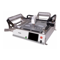
1.1. Brief Introduction.....................................................................................................................................1
1.2. Structure of NeoDen 3V...........................................................................................................................2
1.3. Operation Flow Chart...............................................................................................................................3
1.4. Procedure for Making a Programming File............................................................................................. 4
2. Edit on the Operation Interface........................................................................................................................... 5
2.1. PCB Information Interface.......................................................................................................................5
2.1.1. PCB Feed Setting.......................................................................................................................... 5
2.1.2. Panelized First Chip Setup............................................................................................................6
2.1.2.1. Single Board.......................................................................................................................6
2.1.2.2. Panelized Board................................................................................................................. 8
2.1.2.3. Mirror Board...................................................................................................................... 9
2.1.2.4. PCB Angle Correction......................................................................................................11
2.1.2.5. Bad Board Detection........................................................................................................ 11
2.1.3. Component Setting......................................................................................................................12
2.1.3.1. PCB Mark Setting............................................................................................................ 12
2.1.3.2. Manual Programming...................................................................................................... 14
2.1.3.3. Re-Edit............................................................................................................................. 15
2.1.3.4. Import PCB Coordinate File............................................................................................ 16
2.1.4 Feeder Settings............................................................................................................................. 17
2.1.4.1. Feeder Arrangement.........................................................................................................17
2.1.4.2. Feeder Configuration....................................................................................................... 17
2.2. File Mount.............................................................................................................................................. 21
2.3. Manual Test............................................................................................................................................ 22
2.3.1. Placement Head.........................................................................................................................223
2.3.2. Host Control................................................................................................................................ 23
2.3.3. Feeder Test...................................................................................................................................24
2.4. Factory Settings......................................................................................................................................25
2.4.1. Feeder Configuration.................................................................................................................. 26
2.4.2. System Configuration..................................................................................................................27
2.4.2.1 Default Parameters 1 Setting............................................................................................ 27
2.4.2.2. Nozzle Alignment.............................................................................................................28
2.4.2.3. Nozzle 1 and Camera Relative Position.......................................................................... 28
2.5. First Trial and Test..................................................................................................................................29
2.5.1. First Dry Run...............................................................................................................................29
2.5.2. Production Test............................................................................................................................29
2.5.3. Component Inspection................................................................................................................ 29
2.5.3.1. Inspection Items............................................................................................................... 29
2.5.3.2. Inspection Methods.......................................................................................................... 29