Procedure of Disconnecting
Before any work on the disconnection of the inverter, ALWAYS disconnect it from all voltage sources in the described
sequence as following.
1. Disconnect the AC by opening the branch circuit breaker.
2. Disconnect the first AC connector in the branch circuit.
3. Cover the module with an opaque cover.
4. Using a DC current probe, verify there is no current flowing in the DC wires between the PV module and the BDM-
600.
5. Care should be taken when measuring DC currents, most clamp-on meters must be zeroed first and tend to drift
with time.
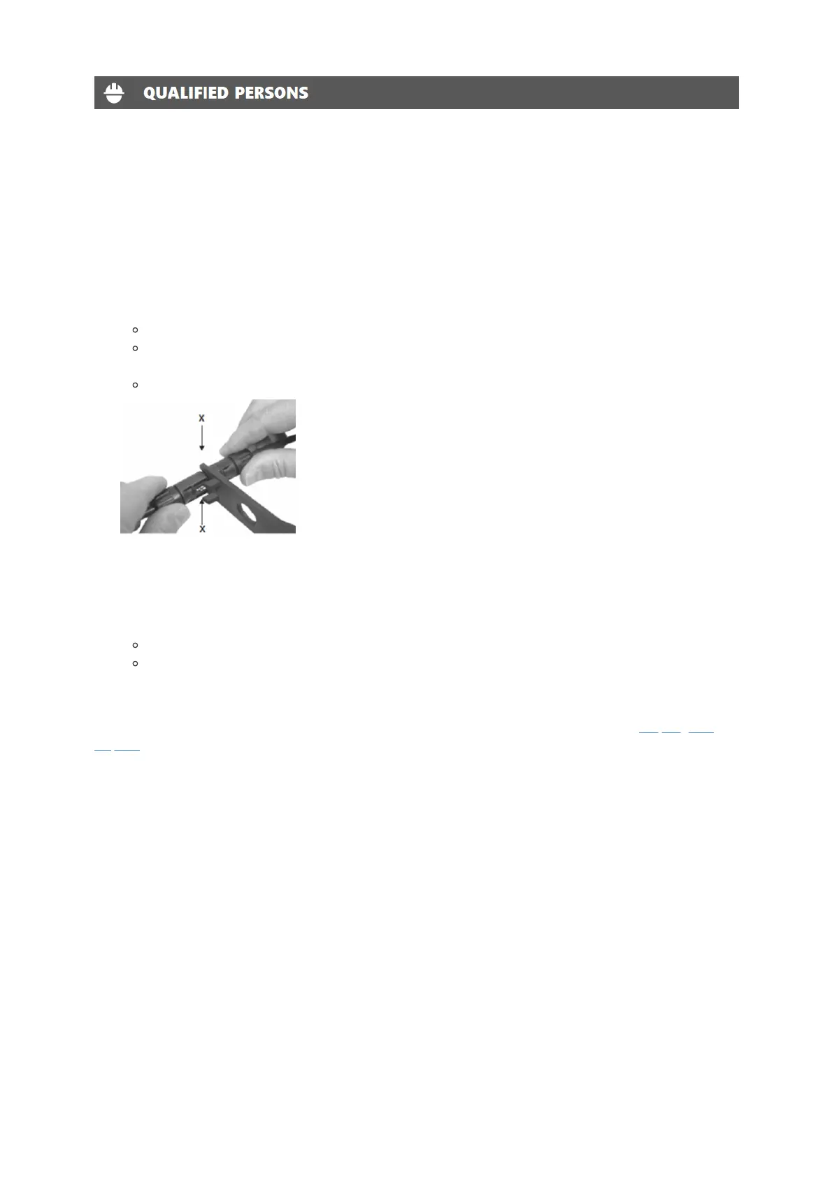
Do not pull on the cable.
Instead, use the disassembly tool for PV connectors at the point of interconnection of female and male
connectors.
Pull out the connectors in a downward direction.
6. Use a suitable measuring device to ensure that no voltage is left at the DC inputs of the inverter.
7. Disconnect the PV module DC wire connectors from the BDM-600.
8. Remove the BDM-600 from the PV array racking.
9. Use a suitable measuring device to ensure that no voltage is left at the AC inputs.
Measure the voltage by inserting the probe to the opening of each terminal.
Check the voltages between L and N, and between L and PE.
10. If necessary, remove the M5 screw securing the inverter to mounting bracket. Lift the inverter from the mounting
bracket.
Dispose of the inverter should be in accordance with disposal regulations for electronic waste. Refer to Recycling and
Disposal.
Re-install micro inverter
1. Attach the replacement BDM-600 to the PV module racking using hardware recommended by your module racking
vendor
2. Connect the AC cable of the replacement BDM-600 and the neighboring BDM-600 to complete the branch circuit
connections.
3. Complete the connection map and connect the PV Modules.
1. Complete the connection map
2. Each BDM-600 has a removable serial number located on the mounting plate. Enter this serial number into a
BDG-256, and correspond it to a number in the connection map.
3. Connect the PV Modules
4. Completely install all BDM-600 and all system inter-wiring connections prior to installing the PV modules.
1. Mount the PV modules above their corresponding BDM-600. Each BDM-600 comes with two oppositely
sexed DC connectors.
2. First connect the positive DC wire from the PV module to the negatively marked DC connector (male pin) of
the BDM-600. Then connect the negative DC wire from the PV module to the positively marked DC