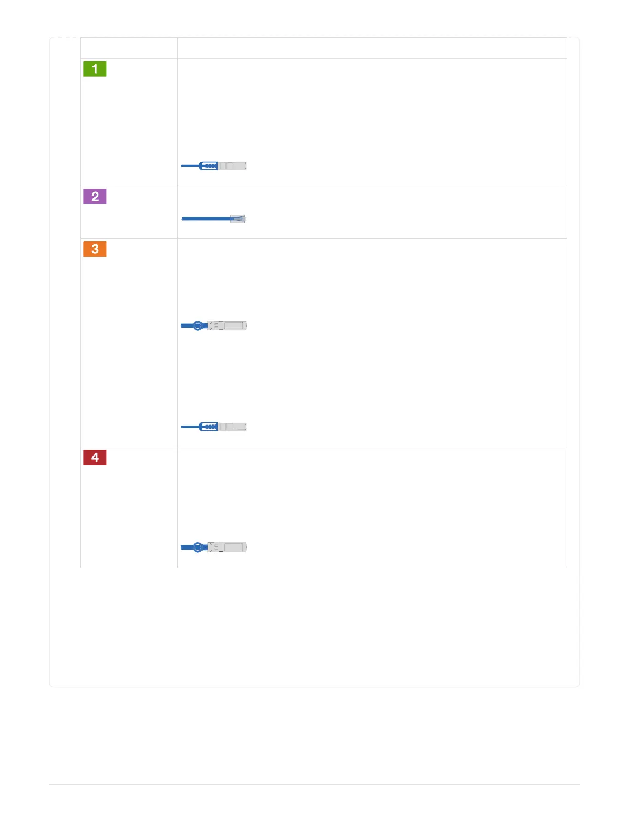
Step Perform on each controller
Cable cluster
interconnect a ports:
• Slot A4 and B4 (e4a) to the cluster network switch.
•
Slot A8 and B8 (e8a) to the
cluster network switch.
Cable controller management (wrench) ports.
Cable 32 Gb FC network switches:
Ports in slot A3 and B3 (e3a and e3c)
and slot A9 and B9 (e9a and e9c) to the
32 Gb FC network switches.
40GbE host network switches:
Cable host‐side b ports in slot A4 and
B4 (e4b) and slot A8 and B8 (e8b) to
the host switch.
Cable 25 GbE connecions:
Cable ports in slot A5 and B5 (5a,
5b, 5c, and 5d) and slot A7 and B7
(7a, 7b, 7c, and 7d) to the
25 GbE network switches.
2.
Connect the power cables to the PSUs
and connect them to different power sources
(not shown).
3.
Strap the cables to the cable
management arms (not shown).
4. To cable your storage, see
Step 4: Cable controllers to drive shelves.
Step 4: Cable controllers to drive shelves
You must cable the shelf-to-shelf connections, and then cable both controllers to the DS212C or DS224C drive
shelves.
691


 To Next Page