Do you have a question about the NETGEAR GS728TPv2 and is the answer not in the manual?
Provides a general overview of the NETGEAR Smart Managed Pro Switches and their capabilities.
Details the key hardware and software features supported by the NETGEAR Smart Managed Pro Switches.
Outlines crucial safety guidelines and warnings for operating and installing the NETGEAR switches.
Describes the physical components and layout of the NETGEAR switch hardware.
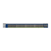
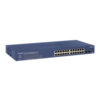
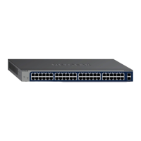
Details the components and LEDs located on the front panel of the switch.
Explains the function and status indication of each LED on the front panel of the switch.
Describes the components and ports located on the back panel of the NETGEAR switch.
Details the various physical ports and connectors available on the NETGEAR switch.
Explains the RJ-45 Ethernet ports, their capabilities, and autosensing features.
Describes the SFP ports used for fiber or copper network connections.
Explains how to use the reset button to reboot the NETGEAR switch.
Details how to restore the switch to its factory default settings using the dedicated button.
Describes the USB 2.0 port for firmware updates, backups, and memory dumps.
Provides an overview of Power over Ethernet (PoE) and PoE+ capabilities of the switch.
Illustrates using the switch for Gigabit aggregation and PoE power sourcing.
Shows examples of connecting PoE devices like cameras and phones in a business setting.
Demonstrates connecting PoE equipment for surveillance and security applications.
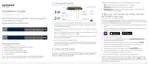
Outlines the site requirements and preparation steps before installing the switch.
Provides instructions on preventing static discharge damage during installation.
Details the process of unpacking the switch and verifying package contents.
Covers the procedures for installing the switch in a rack or on a flat surface.
Optional procedure for installing SFP transceiver modules into the switch's SFP ports.
Guides on connecting network devices to the switch's RJ-45 ports.
Steps to verify the installation before applying power to the switch.
Instructions for powering on the switch and checking the status LEDs.
Information on accessing and using the switch's management interface for configuration.
A table listing common symptoms, causes, and solutions for switch problems.
Tips and solutions for resolving issues related to Power over Ethernet (PoE) functionality.
Further suggestions for resolving persistent or complex troubleshooting issues.
| Switch type | Managed |
|---|---|
| Switch layer | L3 |
| Quality of Service (QoS) support | Yes |
| Product color | Black |
| Rack mounting | No |
| Number of fans | 2 fan(s) |
| Basic switching RJ-45 Ethernet ports type | Fast Ethernet (10/100) |
| Basic switching RJ-45 Ethernet ports quantity | 24 |
| Total Power over Ethernet (PoE) budget | 190 W |
| MAC address table | 16 entries |
| Packet buffer memory | 1.5 MB |
| Number of static routes | 32 |
| 10G support | - |
| Number of VLANs | 256 |
| Networking standards | IEEE 802.1D, IEEE 802.1Q, IEEE 802.1ab, IEEE 802.1w, IEEE 802.3az, IEEE 802.3x |
| Virtual LAN features | Voice VLAN |
| Power source | AC |
| AC input voltage | 100 - 240 V |
| AC input frequency | 50 - 60 Hz |
| Power consumption (max) | 226 W |
| Noise level | 27.08 dB |
| Operating temperature (T-T) | 0 - 50 °C |
| Authentication | Guest VLAN |
| Authentication type | IEEE 802.1x, TACACS+ |
| MAC address entries | Dynamic MAC address entries |
| Security algorithms | HTTPS, MD5, SNMP, SNMPv2, SNMPv3, TLS |
| Queue scheduling algorithms | Weighted Round Robin (WRR) |
| IPv4 & IPv6 features | IPv4/IPv6 access-control list (ACL) |
| Depth | 257 mm |
|---|---|
| Width | 440 mm |
| Height | 43.2 mm |
| Weight | 3780 g |