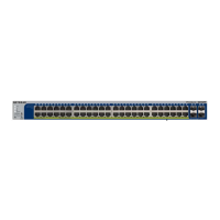
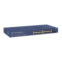
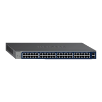
Table 1. Front panel
DescriptionNumber
For more information, see LEDs on page 12.Power LED1
Fan LED2
PoE Max LED3
LED Mode LEDs4
LED Mode button.This button lets you change the information that the port LEDs provide, which is either
switching information (link, speed, and activity) or PoE information (PoE-powered and PoE fault).
For more information, see LEDs on page 12.
5
Reset button.
For more information, see Reset Button on page 14.
6
Factory Defaults button.
For more information, see Factory Defaults Button on page 14.
7
USB 2.0 port for firmware updates, configuration backups, and memory dumps.
For more information, see USB Port on page 14.
8
24 or 48 LEDs associated with the Ethernet ports. Depending on the position of the LED Mode button, the
LEDs provide either switching information or PoE information.
For more information, see LEDs on page 12.
9
4 LEDs associated with the 4 SFP ports. For each port, the associated LED functions as the combined link
and activity LED.
For more information, see LEDs on page 12.
10
24 or 48 independent 10/100/1000BASE-T RJ-45 PoE ports.
For more information, see RJ-45 Ports for 10/100/1000M BASE-T Ethernet Connectivity on page 13.
11
4 dedicated SFP ports in which you can install GBICs for fiber or copper connections.
For more information, see SFP Ports for Fiber or Copper Connectivity on page 14.
12
Hardware Overview
11
24-Port and 48-Port Gigabit PoE+ Smart Managed Pro Switches with 4 SFP Ports

 Loading...