GS716T/GS724T Hardware Installation Guide
2-6 Physical Description
v1.0, June 2009
• System LEDs
Figure 2-2 illustrates the NETGEAR GS716T Smart Switch back panel:
The back panel contains the following:
• A 100-240VAC/50-60 Hz universal input, which is a standard AC power receptacle for
accommodating the supplied power cord.
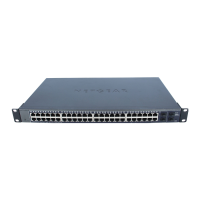
GS724T Front and Back Panel Configuration
The GS724T is a 24-port 10/100/1000 Mbps Smart Switch + 2 SFP Combo ports switch. Every
RJ-45 port is capable of sensing the line speed and negotiating the operation duplex mode with the
link partner automatically
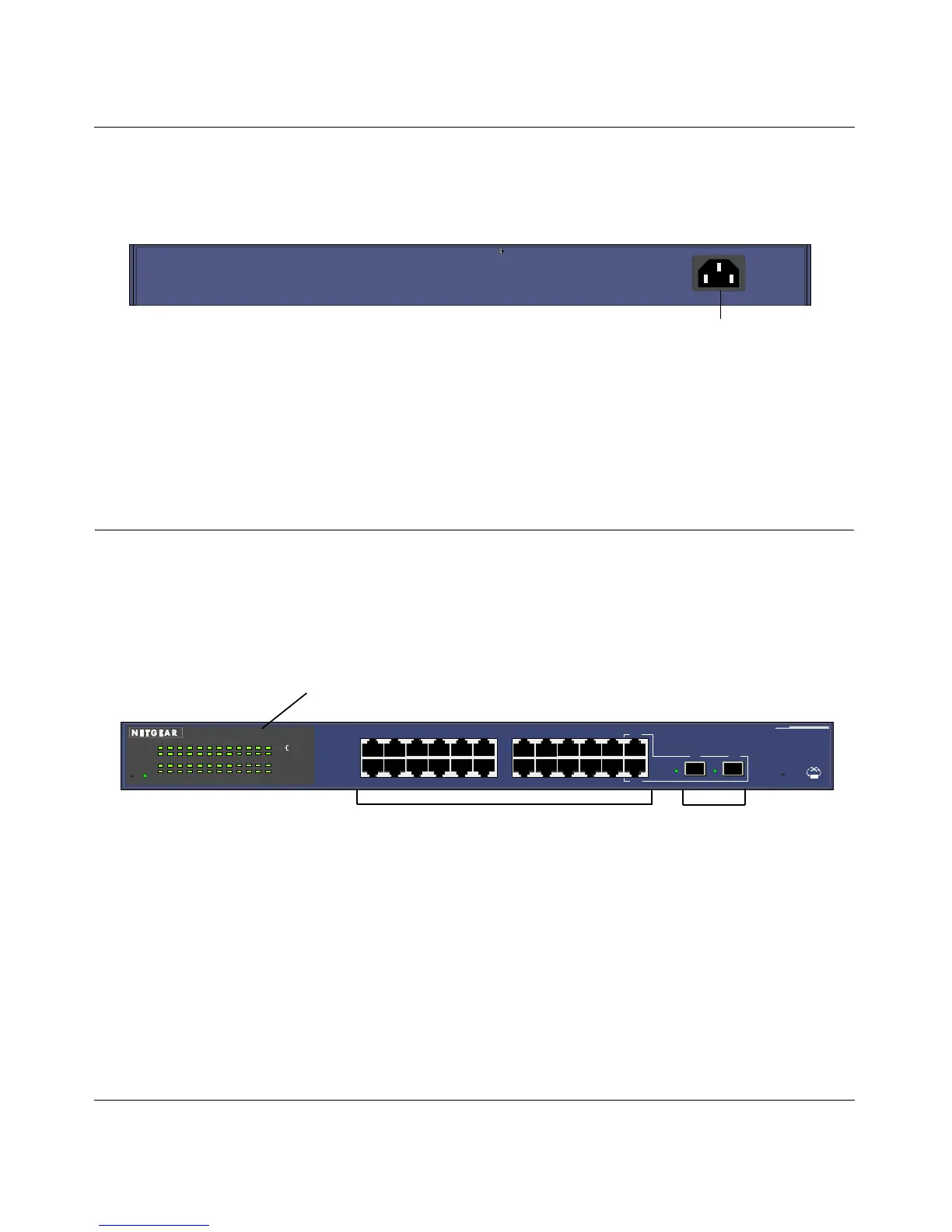
Figure 2-3 illustrates the NETGEAR GS724T Smart Switch front panel:
The front panel contains the following:
• 24 RJ-45 connectors for 10/100/1000 Mbps auto-sensing Gigabit Ethernet switching ports.
• Two slots for SFP slots for SFP modules supporting 1000 (1000BASE-SX/LX)/100 Mbps
SFP.
• Reset button to restart the device.
• Recessed default reset button to restore the device back to the factory defaults.
Figure 2-2
Figure 2-3
 Loading...