Hardware Overview
12
ProSAFE 28-Port and 48-Port 10-Gigabit Smart Managed Switch Models XS728T and XS748T
Back Panel Model XS728T
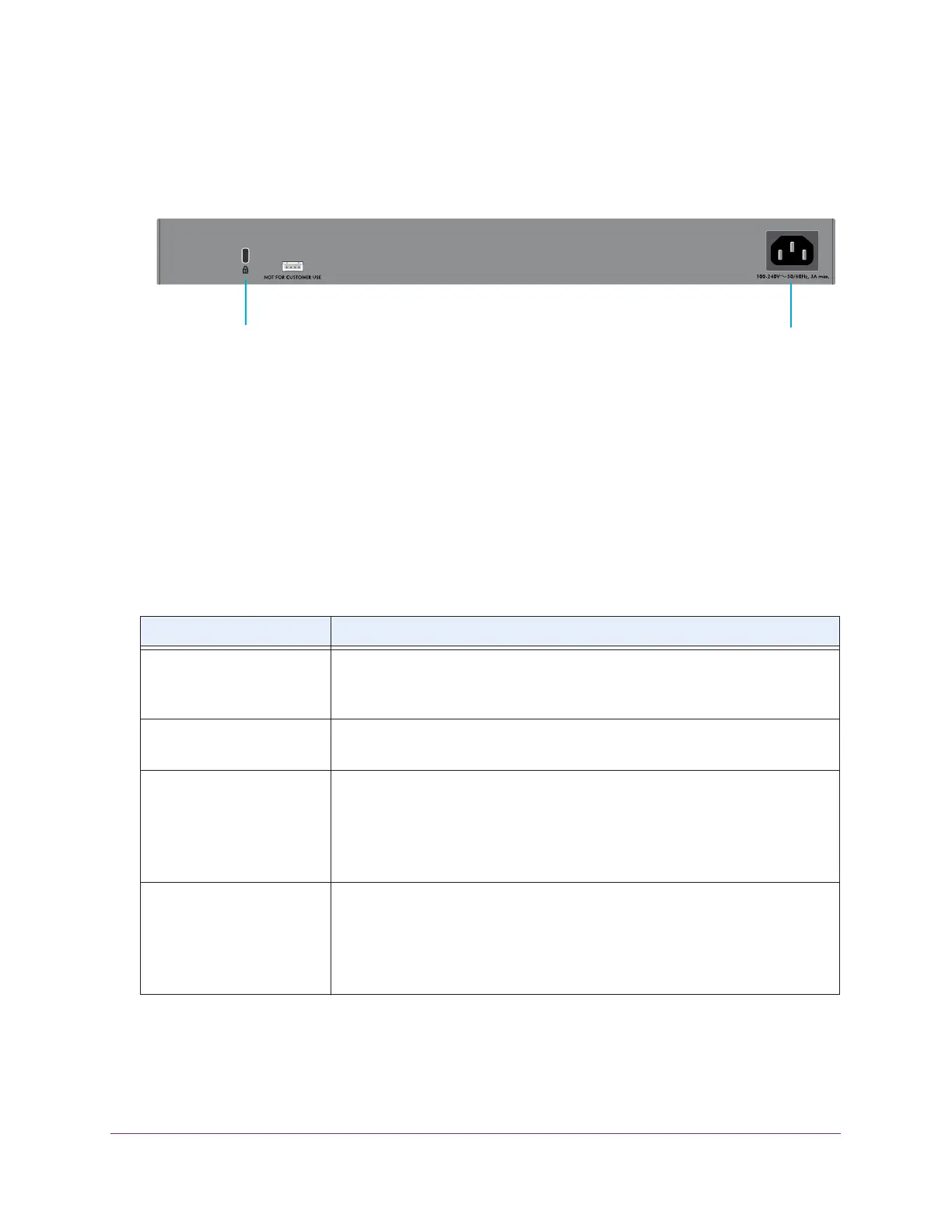
The following figure shows the back panel of model XS728T.
Figure 2. Back panel model XS728T
The back panel contains a Kensington™ lock slot and the AC power connector. The serial
console port is not for customer use.
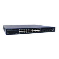
System and Port LEDs Model XS728T
The following table describes the RJ-45 and SFP+ slot LED designations. For each RJ-45
port, the left bicolor LED is for the top port and the right bicolor LED is for the bottom port. For
the SFP+ slots, the port numbers under the slots function as bicolor LEDs.
Table 1. Port and system LEDs model XS728T
LED Designation
Power • Solid green . The device is powered on.
• Solid yellow . The device is booting.
• Off . Power is not supplied to the device.
Fan • Solid yellow . A fan failure occurred.
• Off . The fan is operating normally.
Speed/ACT LEDs for copper
ports 1 to 24
• Off. No link is established.
• Solid green. A valid 10 Gbps link is established.
• Blinking green. The port is transmitting or receiving packets at 10 Gbps.
• Solid yellow . A valid 1 Gbps link is established.
• Blinking yellow. The port is transmitting or receiving traffic at 1 Gbps.
Link/ACT LEDs for SFP+
slots 25 to 28
• Off . No SFP+ module is inserted or no module link is established.
• Solid green. A valid 10 Gbps link is established.
• Blinking green. The module is transmitting or receiving packets at 10 Gbps.
• Solid yellow . A valid 1 Gbps link is established.
• Blinking yellow. The module is transmitting or receiving packets at 1 Gbps.
AC power connector
Kensington lock slot
 Loading...