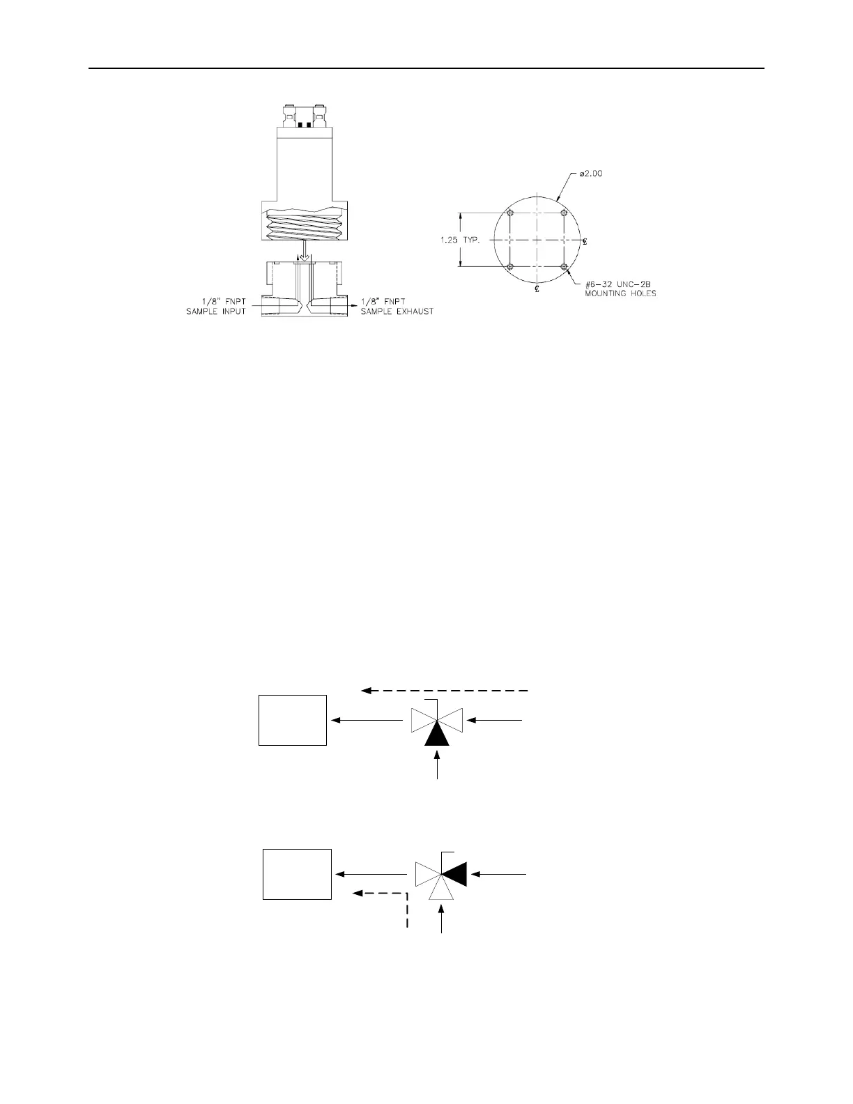
Figure 8b – GP Sensor and flow-through head mounting
2.1.2.2 Sample Inlet Port
Pneumatic connection to the measured process for sample extraction is made at either of the two
interchangeable 1/8" FNPT fitting around the side of the flow-through head. For connecting the
flow-through head to the measured process, use 1/8" or 1/4" rigid tubing, and 1/8" MNPT fittings of
a material compatible with process gas composition. Ensure that no grease, particulate, or solvent
is present in the tubing during installation. Use thread-tape to seal connections, and prevent
galling. Fix all sample tubing and connectors.
A fixed calibration port may be implemented in the process sampling line by installing a 1/8" or 1/4"
3-way manual ball valve into the sampling line as in figure-9. Use 1/8" or 1/4" rigid tubing and 1/8"
MNPT fittings of a material compatible with process gas composition. Ensure that no grease,
particulate, or solvent is present in the tubing during installation. Use thread-tape to seal
connections, and prevent galling. Fix all sample tubing and connectors.