Model 1100 Operations Manual
Manual Part Number:
C5-06-4900-01-0
Manual File Name:
MN-A-0004
Manual Revision Level: E
ECO: 9760
2.1.2 Step 2 – Install the Remote Sensor
The model 1100 is supplied with a model MAX-250 oxygen sensor, and sensor flow-through head
for connection to a sampled process gas stream, and a sensor interface cable with a rubberized
sheath to protect the sensor and the sensor electrical connector from dust and liquid spray.
The model 1100 can also be supplied with a Neutronics Inc. process Sampling system, built-to-
application. For detailed instructions on remote sensor installation with a Neutronics Inc. Process
Sampling System, please refer to the equipment manual.
CAUTION: The remote mounted sensor contains a weak acid
electrolyte (concentrated acetic acid). Do not attempt to disassemble
the sensor. Any sensor found leaking electrolyte should be disposed of
according to local regulations. See material safety data supplied in the
Appendix of this manual. Any damaged sensor should be replaced with a new unit.
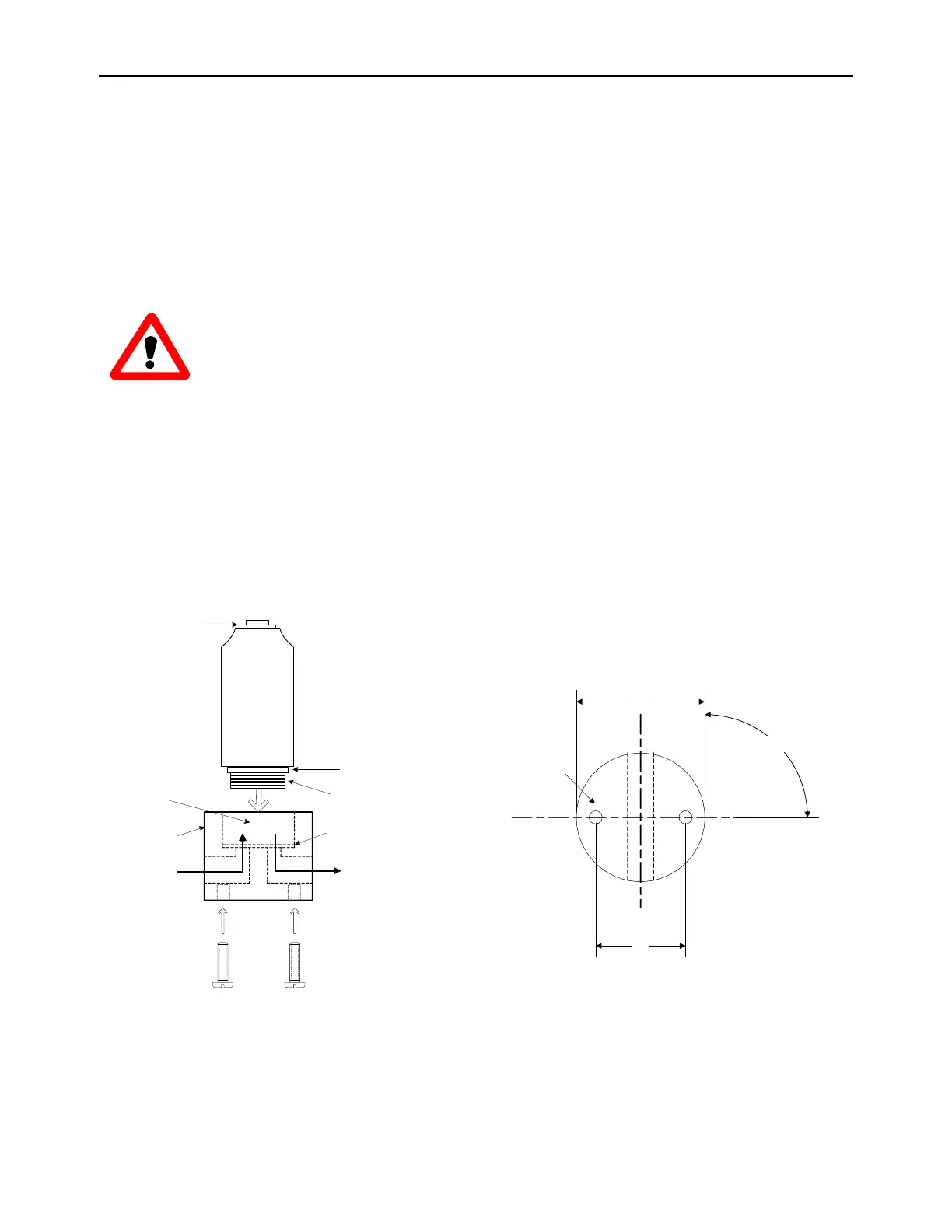
2.1.2.1 Flow-through Head
Surface-mount the flow through head horizontally (as shown in figure 8) or vertically on a
stationary panel. The sensor flow-through head is 1.25" diameter Delrin" plastic or optional
stainless steel, and is machined to accommodate two # 6-32 machine-type mounting screws (1-
inch on center). Be careful not to over tighten the mounting screws. Allow sufficient space to
screw the model MAX-250 oxygen sensor into the top threaded port of the flow through head, and
for the sample lines and sample inlet and exhaust fittings.
!"#$ %&'()
*+,- ./
0 ./1 23
4 526%78329- 8
:.;<%=2<,
>?@A%4 BC7
0;DE5.%)+8;91F
>?@A%4 BC7
0 ;DE5.%G/E9F
!29/FH/-%1I3.61%$
JK$ L&
0 6HFI8I3;MF%JN>&"%E59-
!>K%+%>%F83.;<.<
I2//.IF23
*$ 3H/- % F2E%1 .;5
O;1 P.F
0 ./123
Q.I.EF;I5.
Figure 8a – Max-250 Sensor and flow-through head mounting
C
!
C
!
"#$%
"#&
'() *$+,-./012+$+3405/6 2
789:,;:<+-84/6
=&#&&>