4.1.2.17 220 Volt Line Voltage – NOT USED
4.1.3 Change factory settings via Hardware Jumpers
4.1.3.1 Analog Voltage Output
The Analog voltage output must be configured using the hardware settings. In addition, the
software settings must match the jumper settings. Software changes are made via the Control
panel User Setup menu (section 4.1.1), or the Service Port RS-232 User Setup menu (section
4.1.2.7).
4.1.3.1.1 Remove the unit from service
Make certain that all interfacing to the model 1100 is disabled at the user device. Make sure that
interrupting outputs, from the unit will not interfere with normal process monitoring or control.
Disconnect power from the model 1100 unit. Disconnect the removable terminal blocks from the
rear of the model 1100 chassis. Follow all lock-out/tag-out procedures.
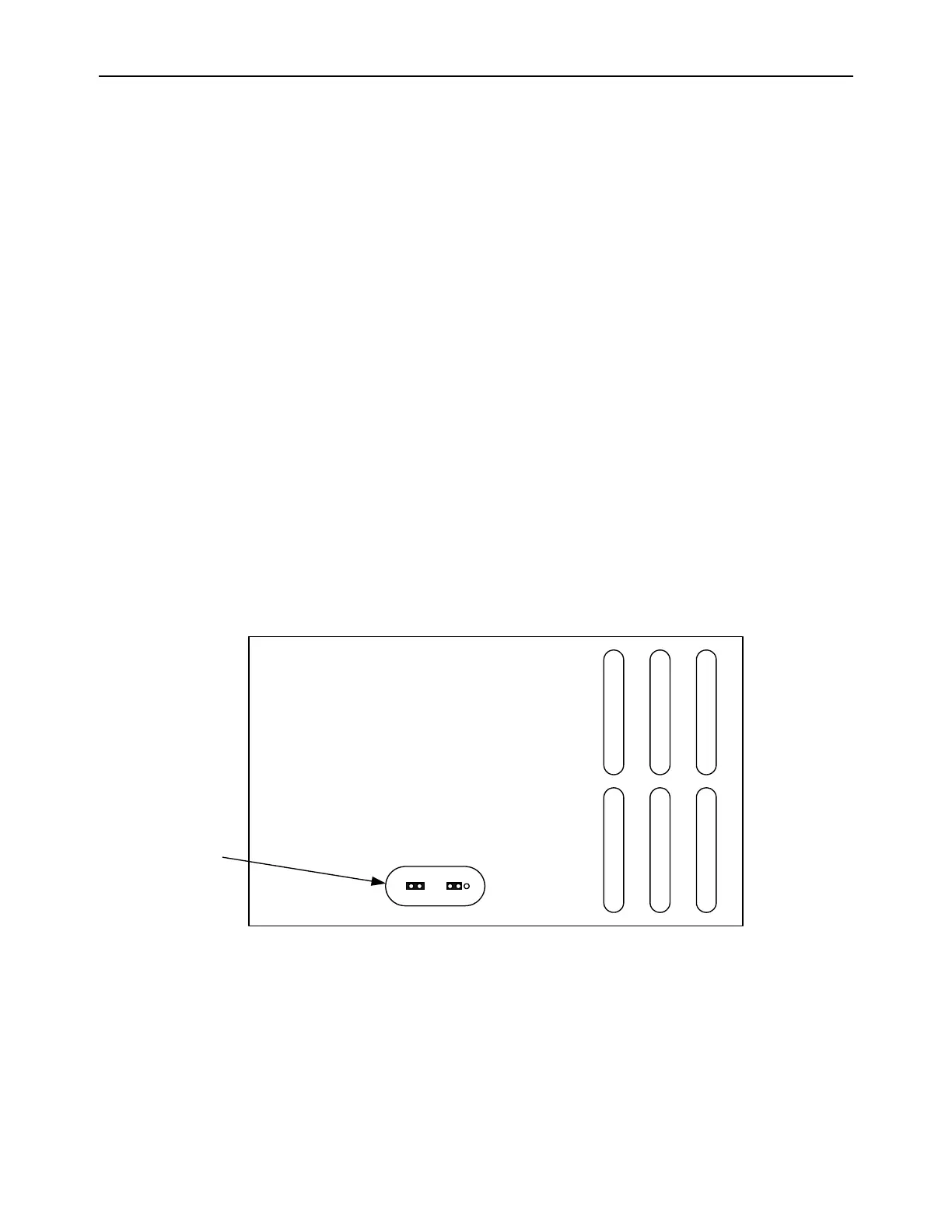
4.1.3.1.2 Change jumper settings
Turn the model 1100 upside down to access the jumpers through the port provided. Identify the
appropriate jumper position. Use an insulated jumper-puller to remove and replace jumpers
(Figure 12).
4.1.3.1.3 Return to service
Replace cables, and terminal blocks. Reapply power. Change Analog Voltage Output setting from
control panel or service port to match new hardware settings. Perform a calibration check. Check
function of changes to ensure the new settings are recognized by the model 1100.