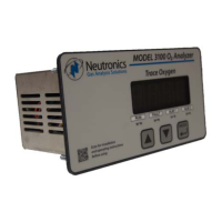
Instruction Manual Model 3100 Analyzer
Manual P/N: C5-06-4900-16-0
Manual file name: MN-A-0005, Rev. C
Page 5
1.4 Analyzer inputs and outputs
Remote sensor module (RSM) interface
1.4.1
A single multi-signal electrical interface (connector) on the back of the Model 3100 analyzer is used to
connect the RSM to the analyzer (see Figure 5). It includes the oxygen sensor input, the sensor heater
thermocouple input, and the sensor heater control output.
1.4.1.1 The oxygen sensor input
The oxygen sensor input is an electrical interface used to indicate the oxygen concentration in the
measured process or in a test gas. It is proportional to the oxygen present in a sampled gas stream.
1.4.1.2 The sensor heater thermocouple input
The sensor heater thermocouple input feeds back a voltage to the Model 3100 analyzer proportional to
the sensor heater temperature. The Model 3100 uses that electrical output to control the sensor heater
temperature within ±0.2° C.
1.4.1.3 Sensor heater control output
The sensor heater control output is a variable frequency control signal, based on the sensor heater
thermocouple input voltage. It controls the sensor heater to operating temperature by varying its average
VAC mains power level continuously. This method of control maintains the oxygen sensor operating
temperature to within its narrow specification at all times, ensuring reliable performance.
Alarm-1 relay output
1.4.2
The Alarm-1 relay is mapped to the Alarm-1 setpoint. The user may set the oxygen level at which Alarm-
1 activates (see section 3.2.2). Alarm-1 may be configured as ascending (highest oxygen level allowable)
or descending (lowest oxygen level allowable) activation. The relay output may be configured for fail-safe
(relay coil de-energized in alarm state) or non-fail-safe (relay coil energized in alarm state) activation.
Factory default settings are ascending, and fail-safe (see Appendix C, Factory Configuration). The
Alarm-1 relay contacts are Form C (DPDT), voltage-free.
Alarm-2 relay output
1.4.3
The Alarm-2 relay is mapped to the Alarm-2 setpoint. The user may set the oxygen level at which Alarm-
2 activates (see section 3.2.3). Alarm-2 may be configured as ascending (highest oxygen level allowable)
or descending (lowest oxygen level allowable) activation. The relay output may be configured for fail-safe
(relay coil de-energized in alarm state) or non-fail-safe (relay coil energized in alarm state) activation.
Factory default settings are ascending, and fail-safe (see Appendix C, Factory Configuration). The
Alarm-2 relay contacts are Form C (DPDT), voltage-free.
Fault relay output
1.4.4
The Fault relay output is used to indicate that there is at least one system fault active on the Model 3100
analyzer (see section 4.3.1). The relay output activation is non fail-safe, and is not configurable. The
Fault relay contacts are Form B (SPST), voltage-free.

 Loading...