Model 3100 Analyzer Instruction Manual
Page 2
Manual file name: MN-A-0005, Rev. C
Manual P/N: C5-06-4900-16-0
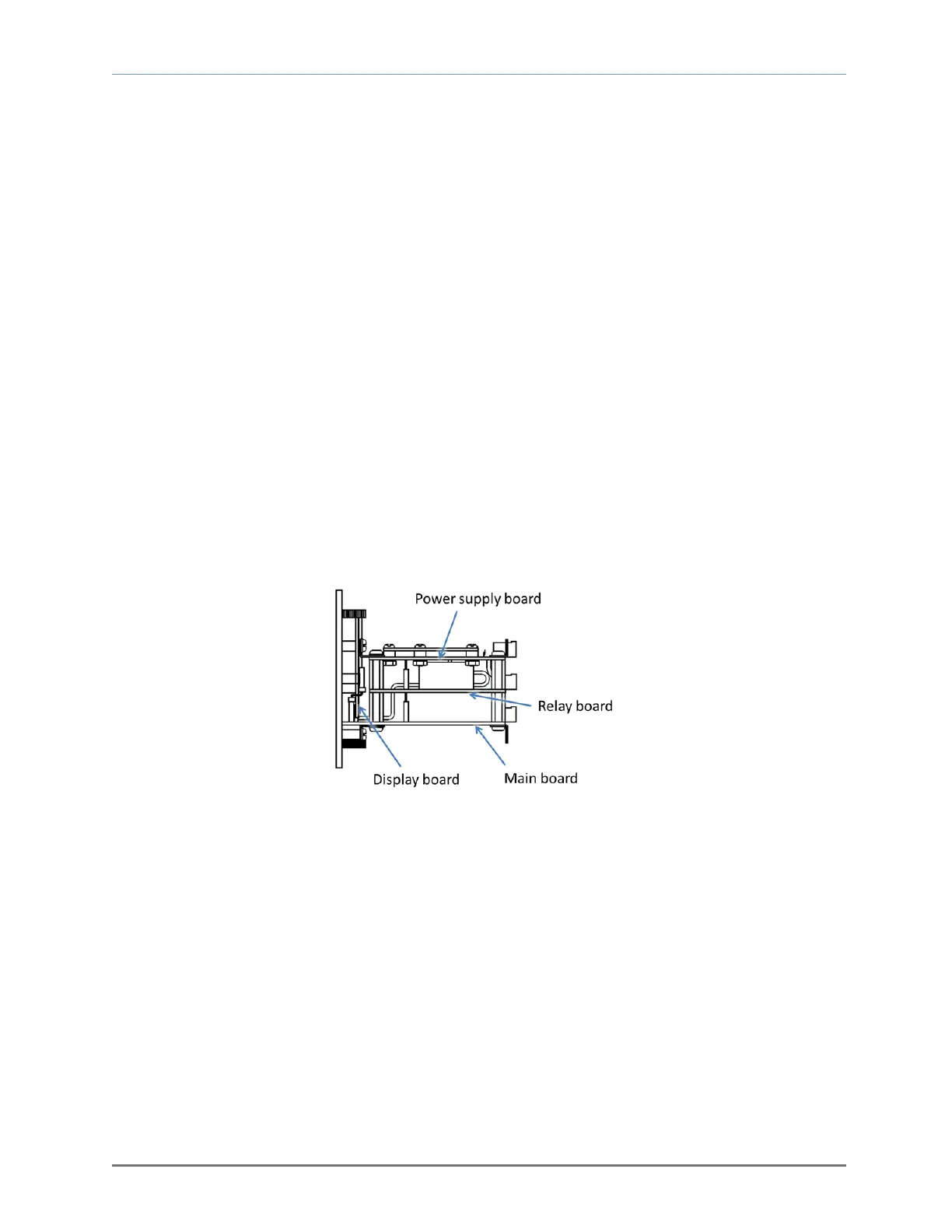
1.3 System hardware overview
1.3.1 Main board
The main board (see Figure 2) houses the microprocessor and supporting electronics for controlling the
operation of the Model 3100 Analyzer. The main board receives the sensor input and provides the
control and display functions of the analyzer.
1.3.2 Relay board
The relay board (see Figure 2) houses relay contacts for all of the alarm and control features. The relays
are mapped discretely to each alarm to provide electrical outputs for reporting and process control use.
1.3.3 Power supply board
The power supply board (see Figure 2) is designed for 110/208 VAC, 50/60 Hz mains power input. The
power supply is fused directly to the board.
1.3.4 Display board
The display board (see Figure 2) is designed to generate a digital indication of the oxygen concentration
(see Appendix E – range / output chart) and fault codes (section 4.3.1). The display is a 7-segment, 0.75"
alphanumeric LED.
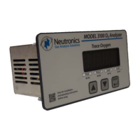
1.3.5 Control panel
The control panel (see Figure 3) serves as the main user interface. It features the menu-driven
pushbutton keypad (ramp-UP, ramp-DOWN, and MODE keys) and the status LED’s. Designed to be
splash and water-resistant, it includes four (4) #8-32 threaded mounting studs at each of the corners and
a gasket for use in mounting the module to a stationary control or equipment panel. The faceplate rating
is NEMA 4, IP66.
Fig. 2, Board configuration