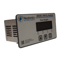
Model 3100 Analyzer Instruction Manual
Page ii
Manual file name: MN-A-0005, Rev. C
Manual P/N: C5-06-4900-16-0
Table of Contents
Welcome ....................................................................................................................................................... iv
Notice ............................................................................................................................................................ iv
Safety instructions ......................................................................................................................................... v
Designated use ............................................................................................................................................. v
Operational safety ......................................................................................................................................... v
1
Introduction............................................................................................................................................ 1
1.1
Functional overview ......................................................................................................................... 1
1.2
Features ........................................................................................................................................... 1
1.3
System hardware overview .............................................................................................................. 2
1.3.1
Main board ............................................................................................................................... 2
1.3.2
Relay board .............................................................................................................................. 2
1.3.3
Power supply board ................................................................................................................. 2
1.3.4
Display board ........................................................................................................................... 2
1.3.5
Control panel ............................................................................................................................ 2
1.3.6
Chassis ..................................................................................................................................... 3
1.3.7
Sensor ...................................................................................................................................... 4
1.3.8
Remote sensor module (RSM) ................................................................................................. 4
1.4
Analyzer inputs and outputs ............................................................................................................. 5
Remote sensor module (RSM) interface .................................................................................. 5
1.4.1
Alarm-1 relay output ................................................................................................................. 5
1.4.2
Alarm-2 relay output ................................................................................................................. 5
1.4.3
Fault relay output...................................................................................................................... 5
1.4.4
Heater OK output ..................................................................................................................... 6
1.4.5
Analog voltage output .............................................................................................................. 6
1.4.6
Analog current output ............................................................................................................... 6
1.4.7
Range ID output ....................................................................................................................... 6
1.4.8
Service port .............................................................................................................................. 6
1.4.9
1.5
Control panel user interface ............................................................................................................. 7
“UP” pushbutton ....................................................................................................................... 7
1.5.1
“DOWN” pushbutton ................................................................................................................. 7
1.5.2
“MODE” pushbutton ................................................................................................................. 7
1.5.3
7-Segment alphanumeric display ............................................................................................. 7
1.5.4
RUN indicator LED ................................................................................................................... 7
1.5.5
Alarm-1 indicator LED .............................................................................................................. 7
1.5.6
Alarm-2 indicator LED .............................................................................................................. 7
1.5.7
Fault indicator LED ................................................................................................................... 7
1.5.8
2
System installation and start-up ............................................................................................................ 8
2.1
Installing the analyzer ...................................................................................................................... 8
Step 1 – Locate the Model 3100 analyzer ............................................................................... 8
2.1.1

 Loading...