Model 3100 Analyzer Instruction Manual
Page 8
Manual file name: MN-A-0005, Rev. C
Manual P/N: C5-06-4900-16-0
2 System installation and start-up
2.1 Installing the analyzer
Step 1 – Locate the Model 3100 analyzer
2.1.1
Select a suitable location for mounting the analyzer where the digital display and status LED’s will
be easy to read and the interface buttons on the display panel will be easy to access
Cut/drill the mounting panel to the specifications shown in Figure 8
Clearance holes for the #8-32 threaded mounting studs do not need to be tapped. Hex nuts are
included for securing the unit to a panel
Trim all burrs or sharp edges in the cut-out or mounting-holes to prevent damage to the gasket
Slide the analyzer unit into the cut-out, rear-chassis first, and seat the control panel gasket on the
mounting surface. The gasket on the analyzer control panel ensures a watertight seal around the
control panel cut-out.
Secure the threaded mounting studs with the supplied hex-nuts and studded lock-washers. The
analyzer control panel is suitable for NEMA Type 4, IP20 environments when properly installed.
The rear electronics chassis is suitable for NEMA Type 1, IP 20 environments.
Ensure the analyzer unit is mounted in an area of free airflow to prevent the chassis from
exceeding the operating temperature specifications.
Locate the unit away from hot surfaces
Allow sufficient distance from adjacent surfaces to prevent blockage of the ventilation holes in the
chassis.
Allow for sufficient free airflow to prevent the chassis from exceeding the operating temperature
specifications (max. ambient temperature of 40°C). Choose an area with a constant source of
ambient air around the unit containing 20.9% oxygen. Higher or lower levels of oxygen
concentration in the atmosphere around the unit will affect system accuracy.
Do not subject the unit to mechanical impact, continuous mechanical vibration, or electrical shock
Do not expose the unit to water, adverse temperatures, or flammable and corrosive gases
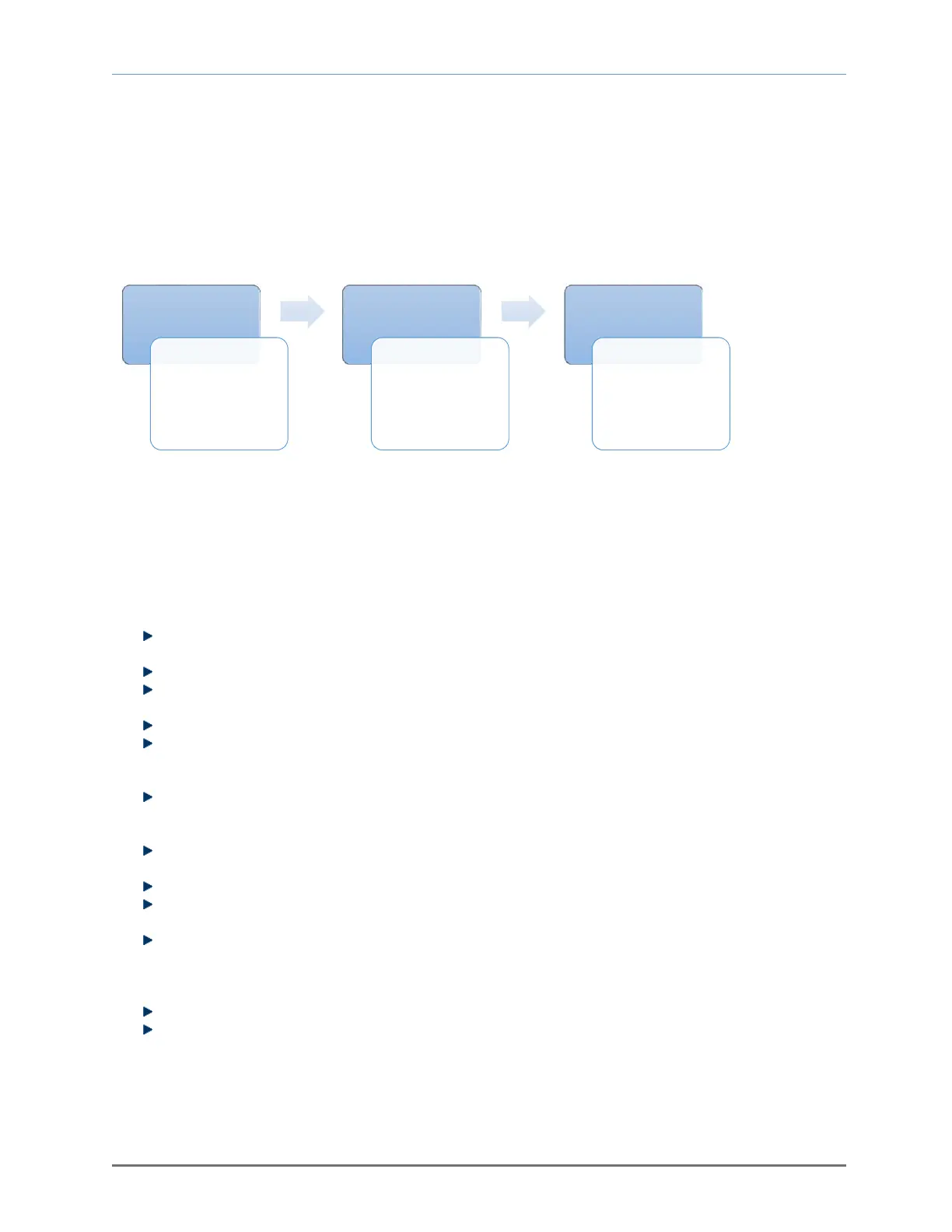
Step1
•Locate
the
analyzer
Step2
•Install
the
analyzer
Step3
•Powerup
the
analyzer
Fig. 7, installation and start-up