Instruction Manual Model 3100 Analyzer
Manual P/N: C5-06-4900-16-0
Manual file name: MN-A-0005, Rev. C
Page 9
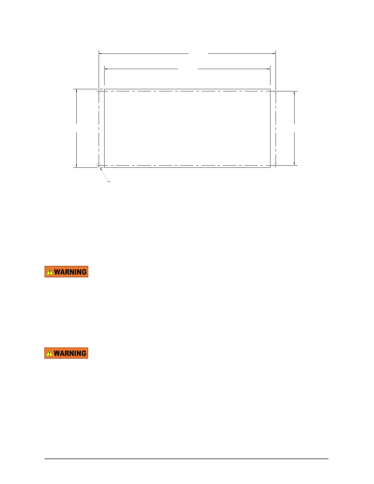
2.91"
6.20"
6.62"
2.75"
PANEL CUTOUT & DRILL PATTERN
.169 DIA. HOLE
4 PLACES
Step 2 – Install the remote sensor module (RSM)
2.1.2
Secure the unit to the mounting surface using the mounting holes in the base plate. For detailed
instructions on RSM installation, please refer to the separate RSM instruction manual.
Step 3 – Install the analyzer
2.1.3
Electrical connections on the rear of the Model 3100 Oxygen analyzer may have
hazardous voltages present once power has been applied to the unit. High voltages may remain present
for a short time even after power has been disconnected from the analyzer. Take care in observing
standard electrical practices when making electrical connections to the Model 3100 Oxygen analyzer.
DANGER: The model 3100 analyzer is not rated intrinsically safe or explosion proof. Be certain that no
flammable gases are present in the area where the Model 3100 analyzer will be installed.
CAUTION: The model 3100 housing is not rated waterproof. Do not mount the analyzer or the sensor in
an area where it may contact water or other liquid elements.
Be certain that all power is OFF to the analyzer and associated wiring (cables) before
attempting installation. DO NOT WORK WITH LIVE WIRES! Do not leave any exposed wire at the
terminal blocks. Before applying power, ensure terminal blocks are fully inserted into the mating
connector at the analyzer.
A label depicting the terminal block arrangement (see Figure 9) is affixed to the top of the chassis for
easy reference during installation and maintenance (208 VAC label is shown for reference only). The
terminal blocks feature screwed terminals. The terminal blocks are also removable for ease of wiring or
removal of the analyzer module).
Fig. 8, Mounting panel cut-out