ChipSHOUTER Users Manual: Specifications
20
While the pulse generator characteristics show that a
wide variety of pulses can be applied to the injection tip,
the actual resulting pulse characteristics will depend con-
siderably on the tip properties itself. It is not possible
to achieve every injection result on every tip.
Insertion of multiple pulses may require adjusting the
driven pulses, which is achieved with the “monitor” port
output. As an example, achieving (approximately) the same
pulses multiple times is shown with the following pattern
trigger waveform setting for 1, 2, and 3 pulses. Note the
spacing between pulses varies as well:
s w 1110
s w 111011110
s w 111000011110000111110
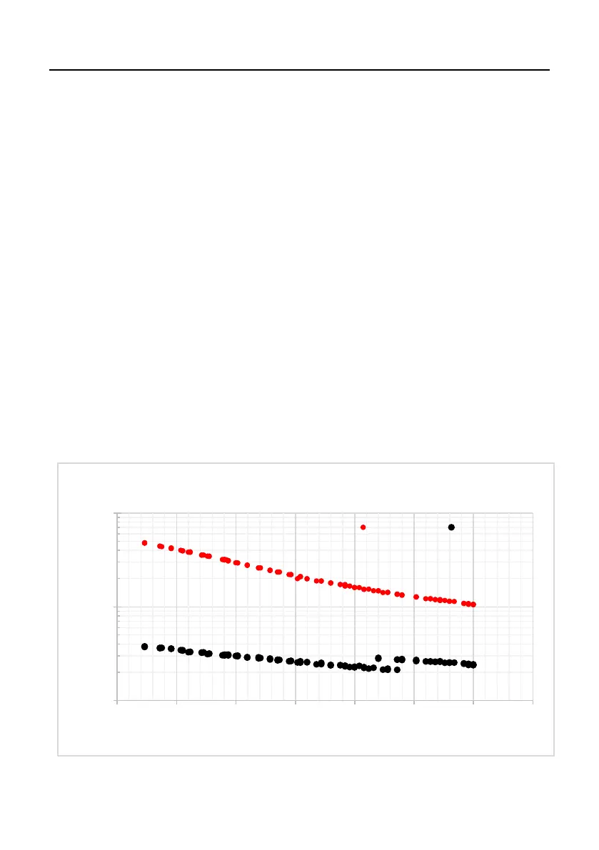
The following figures (Figure 2 and Figure 3) show exam-
ples of possible range of pulses that can be achieved on one
test of the provided 1mm and 4mm tips.
10
100
1000
100 150 200 250 300 350 400 450
Pulse Width (ns)
Peak Output Voltage (Measured)
4mm Tip Pulse Width Limits
Maximum Minimum
Figure 2: 4mm tip pulse width