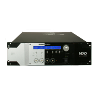
NXAMP4x1
63
5. Inspection with BRIDGE mode
Condition:
• Perform each test item in this section with the bridge test mode of the test program. (See page 57)
• Connect individually the 16 Ω load resistors to channel 1 and channel 3 output terminals.
• Keep the measurement reference of the measuring instrument in floating condition and connect it to the middle point of
each load resistors.
• Do not connect any resistor to channel 2 and channel 4 output terminals.
• The input terminals and output terminals of channel 2 and channel 4 are not used in this section.
5-1. Gain
Input the 1 kHz, 0 dBu sine wave to each input terminal and confirm that the output voltage obtained at each output terminal
is +29.1 ± 1.2 dBu.
5-2. Frequency response
Perform the following test at each channel.
Input the 10 Hz, 1 kHz, 20 kHz, 0 dBu sine wave to the input terminal and one by one measure the output voltage obtained at
the output terminal for each frequency.
Confirm the output voltage at 10 Hz is 0 ± 0.5 dB when compared with the output voltage at 1 kHz (0 dB).
Confirm the output voltage at 20 kHz is +0.5 ± 0.5 dB when compared with the output voltage at 1 kHz (0 dB).

 Loading...