NXAMP4x1
8
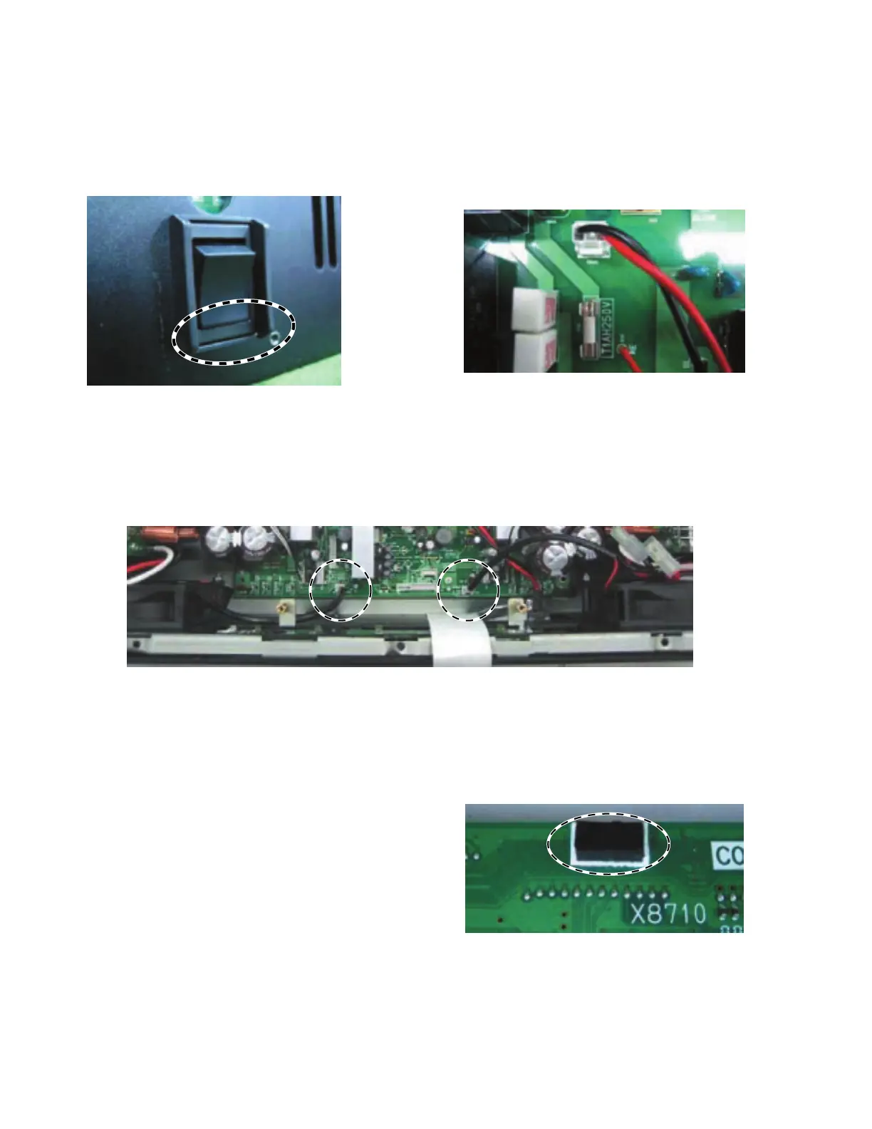
2) Confirm that the power switch is set to the off position as shown in the figure 6. (Fig. 6)
3) Twist the wires of the power switch assembly more than three times.
4) Connect the connector of the power switch assembly to the connector (CN103). (Fig. 7)
Fig. 6
Check
Fig. 7
3. Wiring of the FAN
Connect the connector of the FAN to the each terminal. (Fig. 8)
Fig. 8
4. Attaching of the support cushion
Attach the support cushion (WN15950) at the specified
area on the pattern side of the CONTROL circuit board.
(Fig. 9)
Note: Be sure to remove the oil and the dust, etc. on the
attaching surface before attaching the support
cushion.
Fig. 9

 Loading...


