12
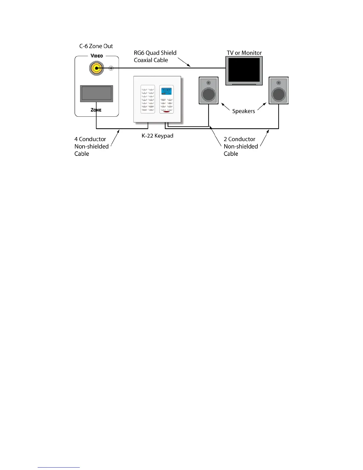
Figure 10. Typical Zone Configuration
Zone Wiring
Keypads/Speakers - Pull four conductor wire in home-runs directly from each keypad location to
the C-6 Controller location. Pull two conductor wire of the same gauge from the keypad location
to each of the speakers in a zone. 16AWG stranded up to 75’; 14AWG stranded up to 100’. Non-
shielded preferred.
NOTE: Min load: 8 ohms per zone. Do not load more than one pair of 8 ohm speakers per zone.
This can cause the unit to go into protection and may possibly blow fuses.
Video – Pull in home runs directly from each possible TV or video display location directly to the
C-6 Controller location. RG6 quad shield preferred. Up to 150’. Terminate with quality gold plated
RCA type male plugs.
Paging
Audio – Use a quality audio cable from the telephone system line audio or paging output to the
Page Audio IN on the C-6 Controller. Line level audio can typically be run up to about 50’.
Anything beyond that should be run through an appropriate balanced line adaptor. Terminate with
a quality gold plated RCA type male plug at the head end and terminate as appropriate for the
paging device used.
Video – Pull RG6 quad shield from device (front door camera, etc.) to be displayed in Page mode
to the C-6 Controller location. If device is local to the controller, an appropriate video patch cable
is acceptable. RG6 quad shield up to about 150’. Terminate with a quality gold plated RCA type
male plug at head end and with connector appropriate to the Page video device to be displayed.
Mute – Pull two conductor stranded wire from the 12VDC output on the device that will trigger
zone muting to the C-6 Controller location. Terminate with a 2.1mm coaxial plug at head end. Pin
= +12VDC, sleeve = ground. 20AWG up to 500’; 18AWG up to 1000’. Non-shielded preferred.
NOTE: Zone mute function must be configured in the C-6 System Setup. See section:
PROGRAMMING – Page/Mute.
Page - Pull two conductor stranded wire from the 12VDC output on the device that will trigger
paging to the C-6 Controller location. Terminate with a 2.1mm coaxial plug at head end. Pin =
+12VDC, sleeve = ground. 20AWG up to 500’; 18AWG up to 1000’. Non-shielded preferred.
NOTE: Paging function must be configured in the C-6 System Setup. See section:
PROGRAMMING – Page/Mute
 Loading...