5
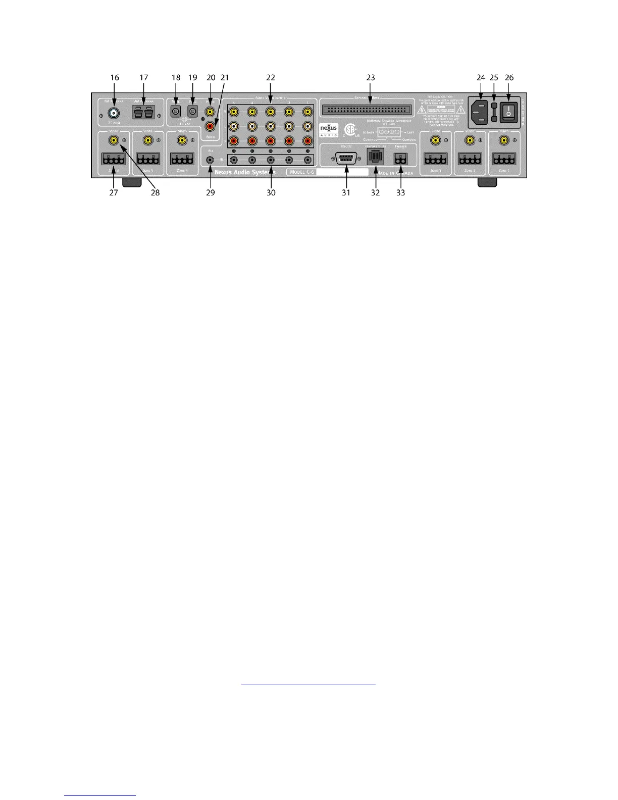
Figure 2. C-6 Controller Rear Panel
Rear Panel
16. FM Antenna – One Female ‘F’ type terminal for connecting an appropriate 75ohm FM
antenna.
17. AM Antenna – One two wire spring clip allows connection of an AM Loop Antenna.
18. Mute – One 2.1mm coaxial jack mutes audio in selected zones as configured in Controller
Setup when 12VDC is present. Polarity: Pin = +12VDC; Sleeve = ground
19. Page – One 2.1mm coaxial jack switches all zones configured for ‘Page’ in Controller Setup
to associated Page Audio and Video jacks when 12VDC is present. Polarity: Polarity: Pin =
+12VDC; Sleeve = ground.
20. Page Audio – One RCA type input jack sends line level audio signal to any zone configured
for ‘Page’ in the Controller Setup when 12VDC is present on the PAGE jack.
21. Paging Video Input – One RCA type input jack sends composite video signal to any zone
configured for ‘Page’ in the Controller Setup when 12VDC is present on the PAGE jack.
22. Audio/Video Inputs – Five sets of RCA type input jacks for composite video and left and
right line level audio signals for up to five external source components.
23. Expansion Buss Terminal – 52 pin terminal distributes audio, video and control signals to
X-1 and X-2 Expansion Controllers for systems up to 18 zones.
24. AC Power – Standard IEC 3-conductor AC line cord receptacle.
25. AC Fuse – T8A L250
26. Main Power Switch – Turns AC power to the C-6 Controller ON/OFF.
27. Zone Keypad/Speaker Terminal – Six plug-in four terminal screw connector terminals for
connecting K-8, K-22 Keypads and speakers in remote zones.
WARNING: THESE ARE NOT TYPICAL SPEAKER TERMINALS. IMPROPER
CONNECTION OF SPEAKERS OR KEYPADS CAN CAUSE DAMAGE TO THE
CONTROLLER, THE KEYPADS AND SPEAKERS. SEE SECTIONS: ‘CONNECTING THE
CONTROLLER - ZONE CONNECTIONS’ AND ‘ZONE CONNECTIONS AND SETUP -
KEYPADS/SPEAKERS’ BEFORE MAKING ANY CONNECTIONS OR TURNING ON THE
MAIN POWER. NEXUS WARRANTY DOES NOT COVER DAMAGE CAUSED BY
IMPROPER CONNECTIONS.
28. Zone Video Output – Six RCA type jacks output composite video to each zone. Maximum
transmission distance: 150’ over RG6 quad shield cable.
29. All – One 3.5mm mini-phone jack outputs IR commands from all sources and all zones.
Polarity: Tip = signal; sleeve = ground.
30. IR – Five 3.5mm mini-phone jacks output routed IR commands to their specific corresponding
source components. Polarity: Tip = signal; sleeve = ground.
31. RS-232 - One DB9 connector provides two-way RS-232 communication with touch screen
controllers, and home automation systems. Pinout: Pin 2 = Tx; Pin 3 = Rx; Pin 5 = ground.
32. Feature Buss – One RJ45 jack, currently inactive, provides future control expansion and
capability. Periodically check www.nexusaudiosystems.com
for updates.
33. 12VDC Trigger Output – One, plug-in, two terminal screw connector, outputs 12VDC @
100mA when any zone is ON.
 Loading...