© National Instruments Corporation 15 NI cDAQ-9178/9174 User Guide and Specifications
Using a Digital Source
To use the Pause Trigger, specify a source and a polarity. The source can be either from PFI or one of
several other internal signals on your NI cDAQ-9178/9174 chassis. Refer to the Device Routing in MAX
topic in the NI-DAQmx Help or the LabVIEW Help for more information.
The NI-DAQmx Help is available after installation from Start»All Programs»National Instruments»
NI-DAQ»NI-DAQmx Help. To view the LabVIEW Help, select Help»Search the LabVIEW Help in
LabVIEW. Alternately, to download the LabVIEW Help, go to ni.com/manuals.
Using an Analog Source
Some C Series I/O modules can generate a trigger based on an analog signal. In NI-DAQmx, this is
called the Analog Comparison Event.
When you use an analog trigger source, the internal sample clock pauses when the Analog Comparison
Event signal is low and resumes when the signal goes high (or vice versa).
Note Pause triggers are only sensitive to the level of the source, not the edge.
Analog Input Timing Signals
Sample Clock
A sample consists of one reading from each channel in the AI task. SampleClock signals the start of a
sample of all analog input channels in the task. SampleClock can be generated from external or internal
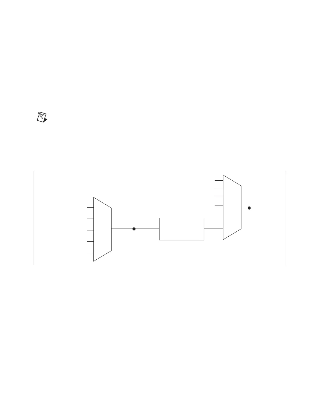
sources as shown in Figure 10.
Figure 10. Sample Clock Timing Options
Routing the Sample Clock to an Output Terminal
You can route SampleClock to any output PFI terminal. SampleClock is an active high pulse by default.
AI Sample Clock Timebase
The AI Sample Clock Timebase signal is divided down to provide a source for SampleClock.
SampleClockTimebase can be generated from external or internal sources. SampleClockTimebase is not
available as an output from the chassis.
AI Convert Clock Behavior For Analog Input Modules
Scanned
Scanned C Series analog input modules contain a single A/D converter and a multiplexer to select
between multiple input channels. When the cDAQ Module Interface receives a Sample Clock pulse, it
begins generating a Convert Clock for each scanned module in the current task. Each Convert Clock
Programmable
Clock
Divider
ai/SampleClock
Timebase
PFI
Analog Comparison Event
Ctr n Internal Output
ai/SampleClock
Sigma-Delta Module Internal Output
Analog Comparison
Event
20 MHz Timebase
80 MHz Timebase
PFI
100 kHz Timebase