© National Instruments Corporation 51 NI cDAQ-9178/9174 User Guide and Specifications
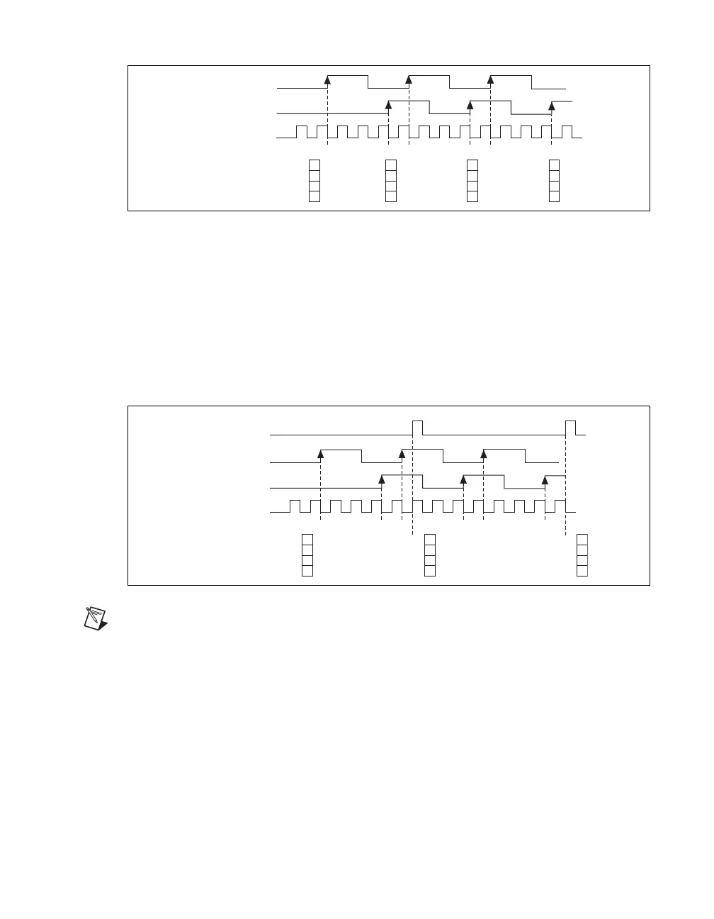
Figure 43 shows an example of an implicit buffered two-signal edge-separation measurement.
Figure 43. Implicit Buffered Two-Signal Edge-Separation Measurement
Sample Clocked Buffered Two-Signal Separation Measurement
A sample clocked buffered two-signal separation measurement is similar to single two-signal separation
measurement, but buffered two-signal separation measurement takes measurements over multiple
intervals correlated to a sample clock. The counter counts the number of rising (or falling) edges on the
Source input occurring between an active edge of the Gate signal and an active edge of the Aux signal.
The counter then stores the count in the FIFO on a sample clock edge. On the next active edge of the
Gate signal, the counter begins another measurement. The USB-STC3 transfers the sampled values to
host memory using a high-speed data stream.
Figure 44 shows an example of a sample clocked buffered two-signal separation measurement.
Figure 44. Sample Clocked Buffered Two-Signal Separation Measurement
Note If an active edge on the Gate and an active edge on the Aux does not occur between sample
clocks, an overrun error occurs.
For information about connecting counter signals, refer to the Default Counter/Timer Routing section.
Counter Output Applications
The following sections list the various counter output applications available on the
NI cDAQ-9178/9174:
• Simple Pulse Generation
• Pulse Train Generation
• Frequency Generation
• Frequency Division
• Pulse Generation for ETS
SOURCE
Counter Value
Buffer
AUX
GATE
123 123 123
3
3
3
3
3
3
SOURCE
Counter Value
Buffer
AUX
GATE
123 12 3 123
3 3
3
Sample
Clock