© National Instruments Corporation 29 NI cDAQ-9178/9174 User Guide and Specifications
Digital Output Triggering
Digital output supports two different triggering actions:
• Start Trigger
• Pause Trigger
A digital or digital trigger can initiate these actions. Any PFI terminal can supply a digital trigger,
and some C Series analog modules can supply an analog trigger. For more information, refer to the
Minimizing Glitches on the Output Signal section of this document or to the documentation included
with your C Series I/O module(s).
Digital Output Timing Signals
The NI cDAQ-9178/9174 chassis features the following DO timing signals:
• DO Sample Clock Timebase
• DO Start Trigger
• DO Pause Trigger
DO Sample Clock Signal
The DO Sample Clock (do/SampleClock) signals when all the digital output channels in the task update.
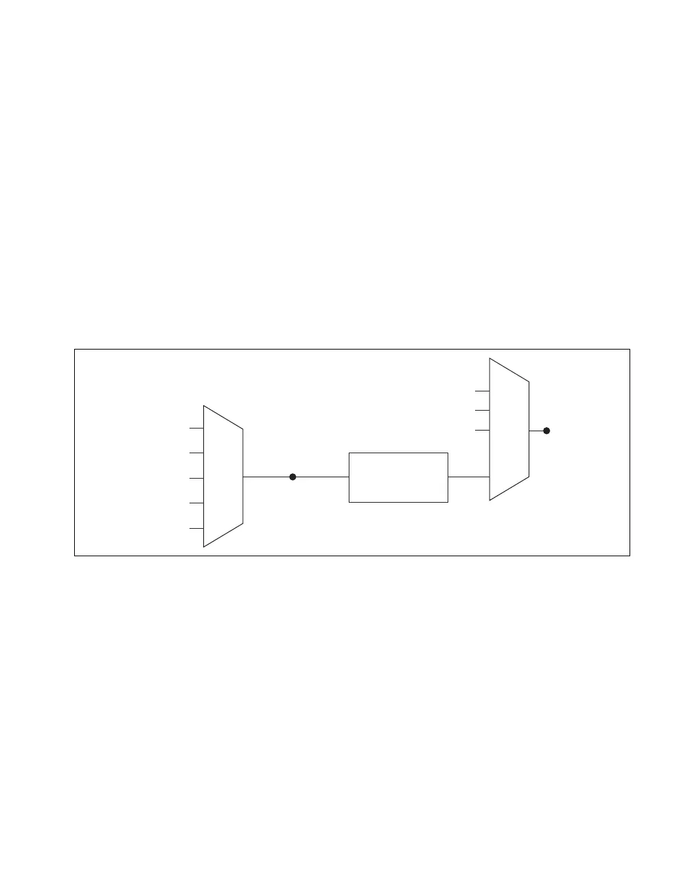
do/SampleClock can be generated from external or internal sources as shown in Figure 17.
Figure 17. Digital Output Timing Options
Routing DO Sample Clock to an Output Terminal
You can route do/SampleClock to any output PFI terminal. do/SampleClock is active low by default.
DO Sample Clock Timebase Signal
The DO Sample Clock Timebase (do/SampleClockTimebase) signal is divided down to provide a source
for do/SampleClock. do/SampleClockTimebase can be generated from external or internal sources, and
is not available as an output from the chassis.
DO Start Trigger Signal
Use the DO Start Trigger (do/StartTrigger) signal to initiate a waveform generation. If you do not use
triggers, you can begin a generation with a software command. If you are using an internal sample clock,
you can specify a delay from the start trigger to the first sample. For more information, refer to the
NI-DAQmx Help. The NI-DAQmx Help is available after installation from Start»All Programs»
National Instruments»NI-DAQ»NI-DAQmx Help.
Programmable
Clock
Divider
do/SampleClock
Timebase
PFI
Analog Comparison Event
Ctr
n
Internal Output
do/SampleClock
Analog Comparison
Event
20 MHz Timebase
80 MHz Timebase
PFI
100 kHz Timebase