© National Instruments Corporation 57 NI cDAQ-9178/9174 User Guide and Specifications
Regeneration is the repetition of the data that is already in the buffer.
Standard regeneration is when data from the PC buffer is continually downloaded to the FIFO to be
written out. New data can be written to the PC buffer at any time without disrupting the output. With
FIFO regeneration, the entire buffer is downloaded to the FIFO and regenerated from there. Once the
data is downloaded, new data cannot be written to the FIFO. To use FIFO regeneration, the entire buffer
must fit within the FIFO size. The advantage of using FIFO regeneration is that it does not require
communication with the main host memory once the operation is started, thereby preventing any
problems that may occur due to excessive bus traffic.
With non-regeneration, old data is not repeated. New data must be continually written to the buffer. If
the program does not write new data to the buffer at a fast enough rate to keep up with the generation,
the buffer underflows and causes an error.
Continuous Buffered Sample Clocked Pulse Train Generation
This function generates a continuous train of pulses with variable idle and active times. Instead of
generating a set number of data samples and stopping, a continuous generation continues until you stop
the operation. Each point you write specifies pulse specifications that are updated with each sample
clock. When a sample clock occurs, the current pulse finishes generation and the next pulse uses the next
sample specifications.
Frequency Generation
You can generate a frequency by using a counter in pulse train generation mode or by using the
frequency generator circuit, as described in the Using the Frequency Generator section.
Using the Frequency Generator
The frequency generator can output a square wave at many different frequencies. The frequency
generator is independent of the four general-purpose 32-bit counter/timer modules on the
NI cDAQ-9178/9174.
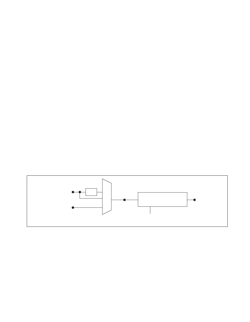
Figure 53 shows a block diagram of the frequency generator.
Figure 53. Frequency Generator Block Diagram
The frequency generator generates the Frequency Output signal. The Frequency Output signal is the
Frequency Output Timebase divided by a number you select from 1 to 16. The Frequency Output
Timebase can be either the 20 MHz Timebase, the 20 MHz Timebase divided by 2, or the 100 kHz
Timebase.
The duty cycle of Frequency Output is 50% if the divider is either 1 or an even number. For an odd
divider, suppose the divider is set to D. In this case, Frequency Output is low for (D + 1)/2 cycles and
high for (D – 1)/2 cycles of the Frequency Output Timebase.
100 kHz Timebase
20 MHz Timebase
Frequency
Output
Timebase
FREQ OUT
Divisor
(1–16)
Frequency Generator
÷
2