NI cDAQ-9178/9174 User Guide and Specifications 20 ni.com
The NI-DAQmx Help is available after installation from Start»All Programs»National Instruments»
NI-DAQ»NI-DAQmx Help. To view the LabVIEW Help, select Help»Search the LabVIEW Help in
LabVIEW. Alternately, to download the LabVIEW Help, go to ni.com/manuals.
You also can specify whether the waveform generation begins on the rising edge or falling edge of
ao/StartTrigger.
Using an Analog Source
Some C Series I/O modules can generate a trigger based on an analog signal. In NI-DAQmx, this is
called the Analog Comparison Event, depending on the trigger properties.
When you use an analog trigger source, the waveform generation begins on the first rising or falling edge
of the Analog Comparison Event signal, depending on the trigger properties. The analog trigger circuit
must be configured by a simultaneously running analog input task.
Routing AO Start Trigger Signal to an Output Terminal
You can route ao/StartTrigger to any output PFI terminal. The output is an active high pulse.
AO Pause Trigger Signal
Use the AO Pause Trigger signal (ao/PauseTrigger) to mask off samples in a DAQ sequence. When
ao/PauseTrigger is active, no samples occur, but ao/PauseTrigger does not stop a sample that is in
progress. The pause does not take effect until the beginning of the next sample.
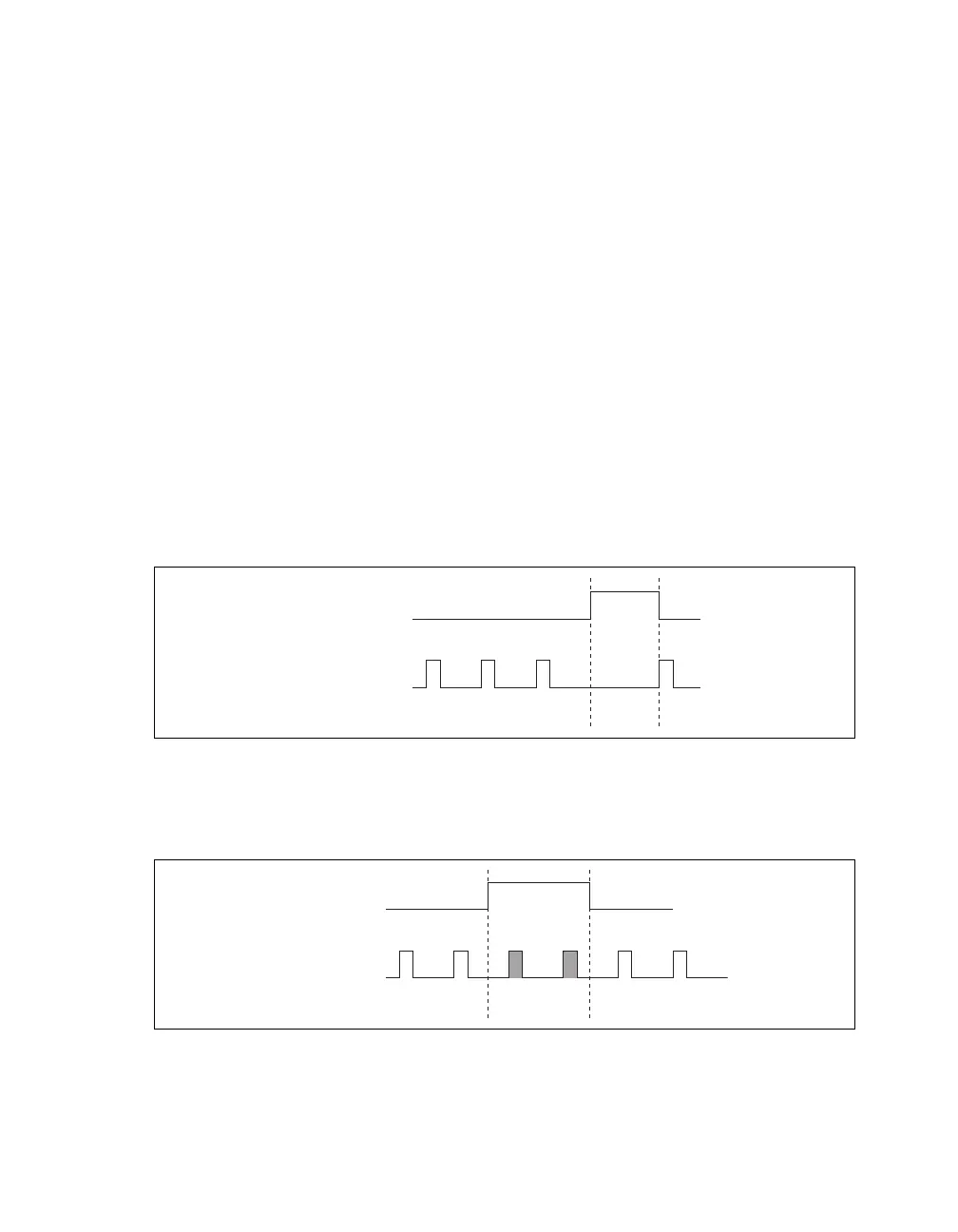
When you generate analog output signals, the generation pauses as soon as the pause trigger is asserted.
If the source of the sample clock is the onboard clock, the generation resumes as soon as the pause
trigger is deasserted, as shown in Figure 12.
Figure 12. ao/PauseTrigger with the Onboard Clock Source
If you are using any signal other than the onboard clock as the source of the sample clock, the generation
resumes as soon as the pause trigger is deasserted and another edge of the sample clock is received, as
shown in Figure 13.
Figure 13. ao/PauseTrigger with Other Signal Source
Pause Trigger
Sample Clock
Pause Trigger
Sample Clock