© National Instruments Corporation 49 NI cDAQ-9178/9174 User Guide and Specifications
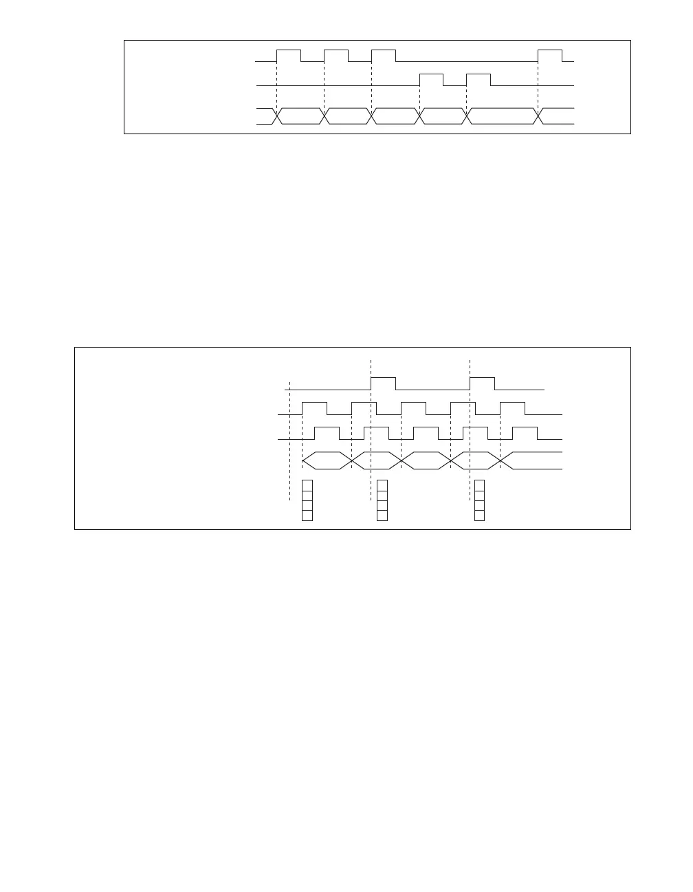
Figure 40. Measurements Using Two Pulse Encoders
For information about connecting counter signals, refer to the Default Counter/Timer Routing section.
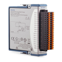
Buffered (Sample Clock) Position Measurement
With buffered position measurement (position measurement using a sample clock), the counter
increments based on the encoding used after the counter is armed. The value of the counter is sampled
on each active edge of a sample clock. The USB-STC3 transfers the sampled values to host memory
using a high-speed data stream. The count values returned are the cumulative counts since the counter
armed event; that is, the sample clock does not reset the counter. You can route the counter sample clock
to the Gate input of the counter. You can configure the counter to sample on the rising or falling edge of
the sample clock.
Figure 41 shows an example of a buffered X1 position measurement.
Figure 41. Buffered Position Measurement
Two-Signal Edge-Separation Measurement
Two-signal edge-separation measurement is similar to pulse-width measurement, except that there are
two measurement signals—Aux and Gate. An active edge on the Aux input starts the counting and an
active edge on the Gate input stops the counting. You must arm a counter to begin a two edge separation
measurement.
After the counter has been armed and an active edge occurs on the Aux input, the counter counts the
number of rising (or falling) edges on the Source. The counter ignores additional edges on the Aux input.
The counter stops counting upon receiving an active edge on the Gate input. The counter stores the count
in the FIFO.
You can configure the rising or falling edge of the Aux input to be the active edge. You can configure
the rising or falling edge of the Gate input to be the active edge.
Ch A
Ch B
Counter Value
2 3 54 34 4
1
3
1
Ch A
Ch B
3102 4
Count
Buffer
Sample Clock
(Sample on Rising Edge)
Counter
Armed