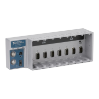
NI cDAQ-9178/9174 User Guide and Specifications 60 ni.com
Counter n Source Signal
The selected edge of the Counter n Source signal increments and decrements the counter value
depending on the application the counter is performing. Table 11 lists how this terminal is used in
various applications.
Routing a Signal to Counter n Source
Each counter has independent input selectors for the Counter n Source signal. Any of the following
signals can be routed to the Counter n Source input:
•80MHz Timebase
•20MHz Timebase
• 100 kHz Timebase
• Any PFI terminal
• Analog Comparison Event
• Change Detection Event
In addition, TC or Gate from a counter can be routed to a different counter source.
Some of these options may not be available in some driver software.
Routing Counter n Source to an Output Terminal
You can route Counter n Source out to any PFI terminal.
Counter n Gate Signal
The Counter n Gate signal can perform many different operations depending on the application
including starting and stopping the counter, and saving the counter contents.
Routing a Signal to Counter n Gate
Each counter has independent input selectors for the Counter n Gate signal. Any of the following signals
can be routed to the Counter n Gate input:
• Any PFI terminal
• AI Reference Trigger (ai/ReferenceTrigger)
• AI Start Trigger (ai/StartTrigger)
• AO Sample Clock (ao/SampleClock)
• DI Sample Clock (di/SampleClock)
• DI Reference Trigger (di/ReferenceTrigger)
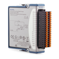
Table 11. Counter Applications and Counter n Source
Application Purpose of Source Terminal
Pulse Generation Counter Timebase
One Counter Time Measurements Counter Timebase
Two Counter Time Measurements Input Terminal
Non-Buffered Edge Counting Input Terminal
Buffered Edge Counting Input Terminal
Two-Edge Separation Counter Timebase